Pumps
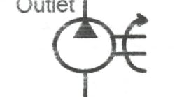
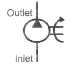
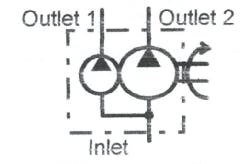
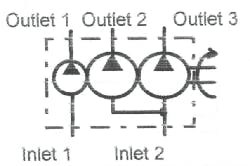
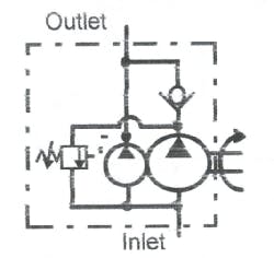
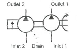
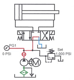
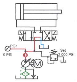
Figures 15-1 through 15-5 show the schematic symbols for several fixed-displacement pumps. Use fixed-displacement pumps in simple, one- or two-cylinder circuits that never stop under pressure. Also use them for single-speed motor circuits, or circuits where several cylinders operate simultaneously but never stop and hold at full pressure. Fixed-displacement pumps always move a set volume of fluid at a pressure between that dictated by resistance and the maximum relief valve setting. Blocking the outlet of a fixed-displacement pump sends excess flow through the relief valve to tank. When fluid goes across the relief valve at pressure, all of the input energy generates heat.
Fixed-displacement pumps may be gear, gerotor, vane, or piston types. The most common are gear and vane. They are relatively inexpensive, very reliable, and generate little heat when used correctly.
Gear and vane pumps come in a wide variety of configurations. Figures 15-1 through 15-3 show one or more pumps in a single housing. The pumps may share a common inlet or have multiple inlets. Most combination pumps have separate outlets for use in different sub-circuits. The flow from each pump in the combination may be the same or different.
Figure 15-4 shows the symbol for a self-contained double pump for a high-low circuit. Flow from both pumps moves an actuator to and from the work at low pressure. The high-volume pump unloads through an integral unloading valve at work contact. This leaves all motor horsepower to drive the low-volume/high-pressure pump. This circuit usually consumes less horsepower without sacrificing cycle time. The packaged pump represented here is compact and inexpensive, but any double pump with the correct valves can supply a high-low circuit.
Many manufacturers produce thru-drive pumps like the one shown in Figure 15-5. A double-shafted electric motor normally operates both pumps. With a thru-drive pump, a second pump is bolted to and driven by the shaft of the first pump. When connecting more than two pumps, consider some possible problems: will the shaft of the first pump handle the torque of additional pumps; will additional pumps result in too much overhung load from too many pumps.
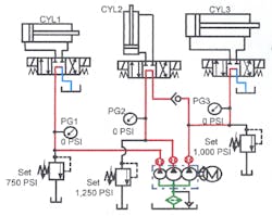
Two pumps supply CYL3 to stroke it rapidly. This circuit works best when CYL2 does not cycle at the same time CYL3 does.
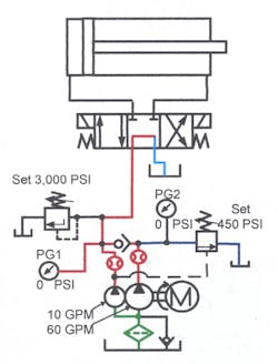
It takes time to design efficient circuits, but the results pay off in future savings. The high-low circuit in Figure 15-8 — which cycles a large fast-stroking cylinder — saves on both first cost and operating cost. If a single 60-gpm pump operating at 3000 psi were used, a 120-hp motor would be required. By substituting a double pump with 60- and 10-gpm sections, the motor size can be reduced without sacrificing cycle time. The big difference occurs because moving the cylinder at say 450 and 500 psi, only requires 20.4 hp. When the cylinder meets resistance and pressure builds to about 500 psi or higher, the 60-gpm pump section unloads at no pressure while the 10-gpm pump does the work. The 10-gpm pump at 3000 psi requires 17.5 hp. Although work speed is slower, travel time is faster. With a little figuring, it’s easy to save money on the electric motor and controls up front, and reduce energy cost for the life of the machine.
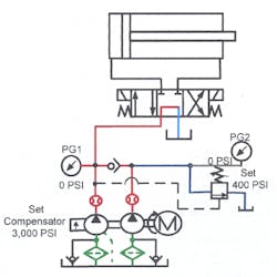
In Figure 15-9, a fixed high-displacement thru-drive pump, coupled with a low-displacement, pressure-compensated pump, creates a different kind of high-low circuit. This circuit provides fast travel and then maintains clamping pressure for extended periods with little heat generation. The circuit operation is the same as Figure 15-8. It requires no special electric controls because the unloading valve automatically dumps the high-displacement pump at any pressure above 400 psi. The low-displacement’ pressure-compensated pump reduces energy cost and heating. This pump arrangement takes the place of a large pressure-compensated pump in certain applications.
Pressure-compensated and variable displacement pumps
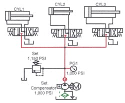
One way to keep from generating heat while maintaining pressure is to use pressure-compensated pumps. Flow from pressure-compensated pumps drops to almost nothing when they reach compensator pressure. Reduced flow cuts horsepower consumption and keeps the system from overheating. Be advised: pressure-compensated pumps are more expensive than fixed-displacement pumps and usually are less contamination tolerant. Also, pressure-compensated pumps only come in vane or piston design. Other pump designs are not capable of variable-displacement while turning the same rotational speed.
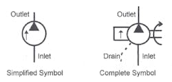
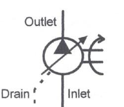
Figure 15-10 shows symbols for a pressure-compensated pump. The arrow inside the circle, parallel to the flow path, indicates pressure compensation. The complete symbol shows all the operating features. The simplified symbol leaves out some details (such as the case drain) and assumes that the person reading the schematic diagram knows their necessity.
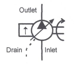
Many pressure-compensated pumps include a method to adjust maximum flow, making the pump more versatile. The symbol in Figure 15-11 indicates a pressure-compensated, variable-displacement pump. The angled arrow through the pump symbol designates variable or adjustable flow. Pressure-compensated pump flow automatically decreases when pressure increases, but the sloping arrow indicates a variable maximum output volume as well. A variable-displacement pump can eliminate the need for flow controls in some circuits.
The variable-displacement pump in Figure 15-12 is not pressure-compensated. Use this type of pump to change the speed of an actuator without wasting energy. Controlling speed this way produces less heat. Control of variable-displacement pumps may be manual, hydraulic, or electrical with servo or proportional valves.
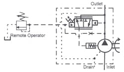
Figure 15-13 shows the symbol for a pressure-compensated pump with a remote operator to adjust maximum pressure. Set the pump compensator for minimum pressure and adjust system pressure at a remote location. This schematic shows a manually adjustable remote relief valve installed near the operator for easy access.
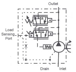
A load-sensing feature can be added to pressure-compensated pumps. Figure 15-14 shows a pump symbol for such a combination. An extra port in the pump samples pressure in the flow lines to the actuator. Sensing actual working pressure causes the pump to compensate to flow demand at pressures 100 to 150 psi higher than working pressure. Load sensing is only advantageous in circuits using less than maximum pump flow. In these circuits load-sensing pumps are more efficient — wasting less energy by and reducing oil heating.
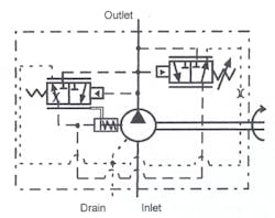
The pump in Figure 15-15 is pressure-compensated with horsepower limiting added. When maximum required pump horsepower can exceed the power of the prime mover, use a horsepower limiter. Horsepower limiting allows the use of a smaller gas or diesel engine with a high volume pump on off road equipment.
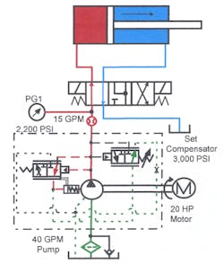
Set the compensator on a horsepower-limiting pump for maximum system pressure at compensated flow. As pressure increases at high flow, the horsepower needed could exceed that available. A horsepower limiter reduces pump displacement at a predetermined pressure. Reducing pump displacement as pressure climbs lowers the horsepower requirement to that available. With this system a 20-hp motor can drive a 60-gpm pump to 5000 psi at reduced flow.
Pressure-compensated, variable-displacement pump circuits
">
To control the speed of an actuator while generating little or no heat, try the circuit in Figure 15-16. A variable-displacement pump controls cylinder speed fairly accurately while using minimum power. As the cylinder strokes, pressure in the system is only what it takes to move the load. All pump flow goes to the cylinder so the only wasted energy is from component inefficiency. A setup like this operates continuously without a heat exchanger. The oil temperature may rise 15 to 25 degrees above ambient temperature only when cycle rates exceed ten or more per minute.
The circuit in Figure 15-17 is a typical pressure-compensated pump setup. This circuit allows multiple cylinders to run separately or together. When the cylinders cycle simultaneously, add flow controls to restrict the actuator that meets the least resistance.
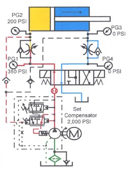
Oil heating can be a problem in pressure-compensated pump circuits. With the pump set at high pressure and/or if flow controls are used in the circuit, energy losses produce excess heat. The efficiency of the directional valves also is a factor. Because the system maintains maximum pressure most of the time, leakage at valve spools adds extra heat.
Pressure-compensated pumps often fail prematurely with high actuator cycle rate. High cycle rates work the compensating mechanism rapidly and resulting pressure spikes can cause part failure. A small accumulator at the pump outlet smoothes the compensator shift cycle, reducing pressure spikes and extending component life.
One way to overcome a heating problem is with the pump in Figure 15-18. When the cylinder cycles, this load-sensing, pressure-compensated pump never allows system pressure to go more than 150 to 200 psi above load demand. The pump constantly senses the load and compensates at that pressure plus the load-sensing spring rate. Load sensing usually eliminates the need for a heat exchanger — even on a system with flow controls.
Run a sensing line from each port in a multiple-actuator circuit. The different feedback lines meet at the pump’s load-sensing port with a check valve to isolate them from each other. The pump always sees the highest load in the circuit and sets output pressure accordingly. A meter-in flow control circuit is the only way to control the actuator. With over-running loads, use a counterbalance valve to keep the actuator from running away.
When driving the pump with an engine — or to save energy with a smaller electric motor — use the horsepower-limiting circuit in Figure 15-19. This circuit changes pump displacement whenever the horsepower required is greater than that called for by the compensator spring setting. The horsepower compensator can be factory set or field adjustable. When system pressure reaches the setting of the pump compensator, output goes to no flow like any pressure-compensated pump.
Bi-directional pumps
Axial- and radial-piston pumps can output fluid from either port while rotating in one direction. Closed-loop circuits take advantage of this feature of piston pumps. A closed-loop pump circuit sends fluid to an actuator while fluid from the same device comes back to the pump’s inlet.
(Do not confuse bi-directional pumps with bi-rotational pumps. Bi-rotational pumps can flow out of either port, but only when rotation reverses. A bi-rotational pump has one port hooked to tank and the other port piped to the circuit. Most bi-rotational pumps operate hydraulic circuits on off-road equipment because rotation of the pump-driving shaft is different from one piece of equipment to another.)
Normally, bi-directional pumps do not have a port piped to tank. Both ports hook directly to the cylinder or motor ports. Many bi-directional circuits operate hydraulic motors, because they accept and return nearly the same amount of fluid. The most common closed-loop circuit is the hydrostatic drive — often used on off-road equipment.
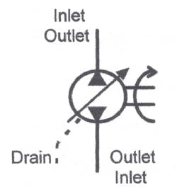
Figure 15-20 shows the schematic symbol for a bi-directional pump. Notice that there are two energy triangles to show that fluid flows out of both ports. The pump only outputs from one port at a time while the opposite port is inlet. With one port hooked to tank and the other port piped to a circuit, the pump serves as a variable-displacement uni-directional pump. Flow direction of a bi-directional pump hooked up this way depends on the position of the stroking control. By changing the position of the stroking control, either port can serve as the inlet or outlet.
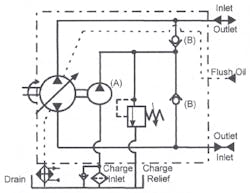
Figure 15-21 shows a hydrostatic transmission — a common bi-directional pump circuit. Small fixed-displacement pump A (called a charge pump) makes up for leakage in the main pump and motor while the circuit operates. Check valves B protect the charge pump and only allow oil into the return side of the closed loop. Charge relief valve C dumps excess charge flow to tank at 150 to 300 psi. Charge pump flow generates heat in hydrostatic systems. Many hydrostatic systems use charge pump fluid to operate pump controls and/or auxiliary circuits.
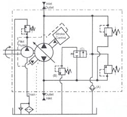
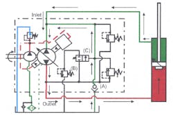
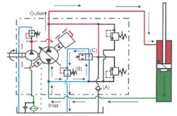
When return flow does not equal output flow, use the bi-directional pump schematic shown in Figure 15-22. With a single-rod end cylinder attached to a bi-directional pump, the volume of fluid going to the cap end when the cylinder extends is greater than the flow returning to the pump from the rod end. When cylinder direction changes, the opposite is true. Without a way to overcome flow inequalities, a bi-directional pump powering a single-rod cylinder would not work.
For single-rod cylinders, add check valve A, low-pressure relief valve B, and NC pilot-operated 2-way valve C to the closed-loop circuit. Check valve A allows the pump to take oil from the tank when the cylinder extends. Relief valve B and 2-way valve C provide a path for excess oil to go to tank when the cylinder retracts.
Often large cylinders operating at high pressure and speed use bi-directional pumps with unequal flow capabilities. This circuit is very efficient and virtually eliminates hydraulic shock
Bi-directional pump circuits
By controlling the volume of flow and its direction from a bi-directional pump, a hydraulic motor can be made to turn in either direction at infinitely variable speeds. A closed-loop circuit wastes very little energy. There is minimum shock when starting or changing direction because the pump starts from and passes through no-flow as it cycles. The hydraulic motor decelerates smoothly when pump flow goes to zero, slowing whatever load it drives.
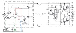
Figure 15-23 shows the parts of a simple hydrostatic transmission that uses this type of circuit. It consists of a variable-displacement bi-directional pump piped to a fixed-displacement bi-directional hydraulic motor in a closed loop. Charge pump A, driven off the bi-directional pump, takes oil from the tank and feeds it through check valves C1 and C2 to keep the closed loop filled. Excess oil from the charge pump discharges across relief valve B to tank. Shuttle valve E and relief valve D send charge flow into the low-pressure side of the closed loop when the hydraulic motor runs. This happens because the set pressure of relief valve D is approximately 100 psi lower than that of relief valve B. Continuous infusion of cool filtered oil protects the closed loop from overheating and contamination.
Cross-port relief valves F1 and F2 protect the pump and motor from excess pressure. When pressure in the closed loop exceeds the relief valve setting, oil bypasses to the opposite line. However, because system volume is small, the flow through the bypass builds heat rapidly. This heat can damage components, hoses, and seals. Most hydrostatic circuits now use valves to destroke the pump at a slightly lower pressure than the cross-port relief valve setting. This destroking valve eliminates pump flow heating but does not help when a driven hydraulic motor acts as a pump.
(Replacing the closed loop circuit with a 4-way directional valve and a fixed-displacement pump with flow controls to vary speed could also operate the hydraulic motor in either direction. This simplified circuit costs about one fifth as much as a hydrostatic transmission. However, the costs of system shock, oil heating, and machine damage caused by the cheaper system far outweigh the original cost savings.)
Using a closed-loop pump with a single-rod cylinder requires additional valving in the pump. Figures 15-24 and 15-25 show a single-acting cylinder circuit operated from a bi-directional closed-open-loop pump. The term closed-open-loop indicates that the pump is bi-directional, but one port is connected to tank through check valve A. This keeps the pump from starving when the cylinder extends. Also, low-pressure relief valve B and NC 2-way valve C provide a path to tank for excess flow from the cylinder cap end when it retracts.
When the cylinder extends as in Figure 15-24, flow from the rod end of the cylinder cannot fill the pump. Because the pump needs more oil than the cylinder supplies, check valve A opens to allow oil from the tank to enter the pump. (Note that large cylinder rods increase the need for flow from the charge pump and tank.)
When the cylinder retracts as in Figure 15-25, oil from the cap end of the cylinder is more than the pump needs. During this part of the cycle, pilot pressure opens NC 2-way valve C to allow excess cylinder flow to pass through low-pressure relief valve B to tank. (Again, the larger the cylinder rod, the greater the volume of oil ported to tank.)
The main reason for using bi-directional pumps is the very smooth control of the actuator they provide. Bi-directional pumps completely control starting, stopping, and reversing of the largest high-speed actuators. This practically eliminates system shock and greatly extends machine life.
