BOOK 2, CHAPTER 18: Pressure-relief valves
Always use a relief valve with fixed-displacement hydraulic pumps. Pressure-compensated pump circuits also may use a relief valve for certain applications.
Think of a relief valve in a hydraulic system as a fuse or circuit breaker in an electric circuit. An electric circuit never blows a fuse unless it overloads. When an electric circuit overloads, it is inoperable until reset. Usually the person responsible for resetting the fuse looks for the reason it blew and fixes the problem before restarting the machine. Many hydraulic circuits allow the relief valve to dump some or all pump flow to tank all or part of the time. The extra power to produce that unused flow is expensive. Also, heat generation from excess flow requires larger heat exchangers that are expensive to buy and operate.
Protecting the pump and the system from excess pressure is the only valid function for a relief valve. At no time should the relief valve be used to pass excess pressure fluid to tank. When excess pump flow goes to tank, it generates heat. The relief valve in a well-designed hydraulic circuit never relieves oil to tank — unless there is a circuit or control malfunction.
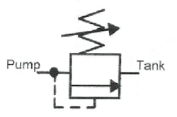
Figure 18-1 pictures the symbol for a direct-acting relief valve. A direct-acting relief valve responds quickly when pressure tries to go above the valve’s setting. It can be use it on circuits with pressure-compensated pumps to reduce pressure spikes. On a hydraulic circuit with a fixed-displacement pump, a direct-acting relief valve opens partially early and thus wastes energy. When the system must operate near maximum pressure without any fluid bypass, use a pilot-operated relief valve.
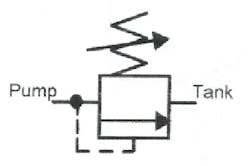
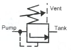
Figures 18-2 and -3 show the simple and complete symbols for a pilot-operated (or compound ) relief valve. This type relief valve has two sections. The pilot operator on top is a small, poppet-type direct-acting relief valve. The main flow section of the valve is a poppet- or piston-type, normally closed 2-way valve. Through internal porting, a small direct-acting relief poppet controls a large poppet or piston. A pilot-operated relief valve responds more slowly, but does not even partially open until system pressure reaches approximately 95% of set pressure. Pilot-operated relief valves are suitable for remote operation, they open to unload pumps at pressures below 50 psi, and they act as large 2-way valves in some circuits.
Examples of relief-valve circuits
Always locate the relief valve as close as possible to the outlet of a fixed-displacement pump. A pilot-operated relief works best because it does not pass any fluid until system pressure is very near the valve’s set pressure.
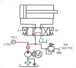
Figure 18-4 shows a typical fixed-displacement pump circuit. Except in the event of a control circuit malfunction or if it is used to hold the cylinder at pressure, the relief valve never opens. Heat generation is minimal and the circuit usually can run without a heat exchanger.
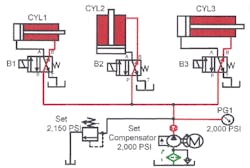
Figure 18-5 shows a pressure-compensated pump with a direct-acting relief valve to protect it against overpressure. Pressure spikes often occur in pressure-compensated pump circuits with high flow or fast cycling. When the pump must compensate rapidly or often from full flow to no flow, the resulting overpressure drastically shortens pump life.
In Figure 18-5, the pump would be at low pressure and full flow when cylinder CYL3 extends rapidly. When the cylinder stops, fluid requirement is zero, but pump flow is still 40 gpm. As pressure builds, the pump finally starts compensating at about 1900 or 1950 psi. It is still producing 40 gpm — with no place for the oil to go. Without a relief valve in the circuit, system pressure spikes during each cycle can reach four to ten times the compensator setting. Pressure spikes damage the pump and piping after a few hours of operation. The faster the cycle, the more quickly shock damage from pressure spikes causes problems.
A relief valve, installed in Figure 18-5, reduces pressure spikes to protect the system. When the pump shifts to no flow, excess flow goes to tank through the relief valve. When the pump reaches compensator pressure, the relief valve closes. (For another and better way to reduce pressure spikes and protect a pressure-compensated pump from rapid cycling, see Chapter 1, Figures 17-19.)
Set the relief valve in a pressure-compensated pump circuit at 150 to 200 psi higher than the pump compensator. With relief pressure below compensator setting, pump flow goes to tank and makes heat. With relief pressure set at compensator pressure, the relief valve starts dumping when the pump starts compensating. When the relief valve passes fluid, the pump sees a pressure drop, and starts flowing again. The resultant pressure drop allows the relief valve to close and the dump/flow cycle starts again. After a few hours of this erratic operation, the pump fails.
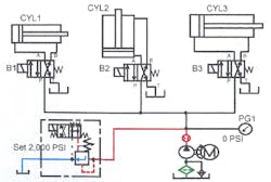
Adding a solenoid valve to the vent port of a pilot-operated relief valve makes an effective unloading valve. Figure 18-6 shows a fixed-displacement pump supplying three cylinders. There is no power to the solenoid on the relief valve with the cylinders idle, so pump flow goes to tank at low pressure. Energizing a solenoid on the relief valve and one cylinder’s directional valve causes an action. Energizing both solenoids at the same time sends pump flow to the cylinder until reaching maximum relief pressure. A solenoid relief valve always has a slight delay before blocking flow to tank after energizing the solenoid. The delay is in milliseconds so it usually is only noticeable on very fast cycles.
The circuit in Figure 18-7 uses a solenoid-operated relief valve to unload the high-volume pump in a hi-lo circuit. Instead of waiting for pressure to build before the high-volume pump dumps to tank, the solenoid relief dumps oil on demand. The demand signal could come from a pressure switch, a limit switch, or an electric eye that senses cylinder position (then slows it before it contacts the work).
A relief valve that decelerates an actuator
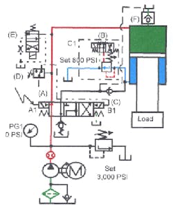
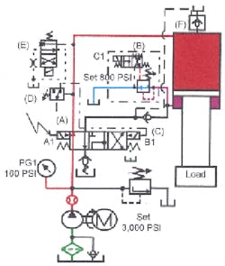
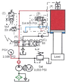
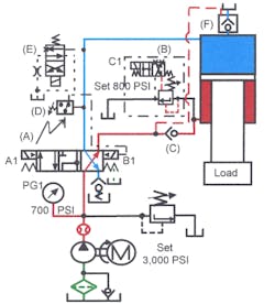
Figures 18-8 through 18-14 show normally closed, solenoid-operated relief valve B used to rapidly extend, then decelerate a free-falling cylinder. Deceleration takes place when the cylinder makes a limit switch that deenergizes the solenoid on relief valve B . Relief pressure should be set 150 to 200 psi higher than the pressure required to raise the cylinder. Any higher relief pressure shortens the deceleration stroke and increases shock.
Figure 18-8 shows a cylinder with its rod port piped to tank through normally closed solenoid-operated relief valve B . Prefill valve F allows the cap end of the cylinder to fill during rapid advance. (See Chapter 7 for an explanation of the prefill valve’s function.) Check valve C at the rod port keeps cylinder flow from going to tank through directional valve A.
To extend the cylinder, energize solenoid A1 on directional valve A to pass oil to the cylinder’s cap end, as in Figure 18-9. Also energize solenoid C1 on relief valve B , venting it to tank and allowing the cylinder to fall freely. As the cylinder falls, the cap end fills from the pump and from tank directly through prefill valve F.
As the cylinder extends, high flow leaving the cylinder’s rod end goes to tank. Just before the rod contacts the work, a limit switch deenergizes solenoid C1 on relief valve B , Figure 18-10. As valve B tries to close, pressure increases in the cylinder’s rod end, keeping the valve partially open. Backpressure from relief valve B quickly and smoothly slows cylinder descent. The cylinder continues to slow while the relief valve shuts. The cylinder does not completely stop because the pump forces it to extend after free fall.
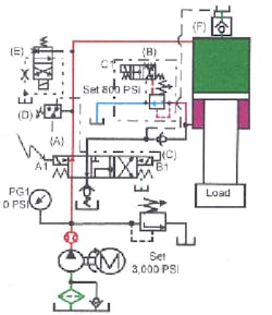
After deceleration, relief valve B acts as a counterbalance valve, as in Figure 18-11, so the load cannot run away. The cylinder extends at pressing speed to the work. This part of the stroke should be as short as possible to save time. Prefill valve F closes as the cylinder decelerates and allows pressure to build in the cap end. The slowdown is smooth and controlled — without shock or bouncing. This circuit decelerates the cylinder when commanded by an electrical signal at any point in its stroke.
Figure 18-12 shows the circuit while the cylinder is pressing. When the cylinder contacts the work, energize solenoid C1 on relief valve B again. Energizing the solenoid on the relief valve lets oil from the cylinder’s rod end flow to tank at minimal pressure. This allows the weight of the platen and tooling to add to the pressing force because they are no longer counterbalanced. Pressure increases in the cylinder’s cap end to perform the work.
Deenergizing solenoid A1 on directional valve A lets it center and decompress the cylinder, Figure 18-13 shows directional valve A centered, blocking the cylinder’s cap-end port and unloading the pump. At the same time, a signal to single-solenoid valve E in the cap-end line shifts it open. Trapped pressurized oil in the cylinder’s cap end flows to tank through an orifice, thus lowering pressure without shock. Pressure switch D indicates when pressure is low enough to shift valve A to retract the cylinder. (See Chapter 7 for an explanation of a decompression circuit. A decompression circuit keeps the cylinder from rapidly losing pressure and shocking the system.)
To retract the cylinder, energize solenoid B1 on directional valve A to send oil to the cylinder’s rod end, as in Figure 18-14. Oil from the pump starts to retract the cylinder. Pilot oil opens prefill valve F to tank. Oil from the cylinder’s cap end flows to tank through the prefill valve and the main directional control valve. The cylinder retracts rapidly at low pressure.
Using solenoid relief valves as 2-way valves
High-flow (above 50 gpm) 2-way valves are not readily available for hydraulic circuits. To get around this problem, use a solenoid relief valve. Several circuits shown here are in use in many hydraulic applications.
For flows above 150 to 200 gpm, use slip-in cartridge valves (as explained in Chapter 4). Slip-in cartridge valves use simple directional controls to operate large poppets that can handle flows in excess of 600 gpm.
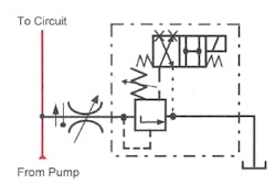
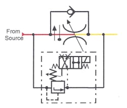
Figures 18-15 through 18-16 show the schematic diagram for a high-flow, on-off, bleed-off flow control circuit. Set the solenoid relief valve higher than system pressure so it never passes fluid unless vented. The normally closed bleed-off circuit shown in Figure 18-15 passes fluid when the solenoid is energized. Figure 18-16 shows a normally open solenoid-operated relief valve. With this valve, energizing the solenoid stops flow.
The circuits in Figures 18-17 and 18-18 show solenoid-operated relief valves bypassing large flow controls in a 2-speed circuit. Because there is backpressure downstream from the solenoid relief valve in this type circuit, use a valve with an external drain. (Backpressure at the outlet of a relief valve causes it to shut when internally drained.) Externally draining the relief valve eliminates backpressure at the vent port so it stays open when bypassing.
Solenoid reliefs used as shut-off valves do not cause as much shock as spool-type valves because relief valves cushion as they close.
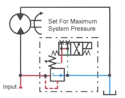
In Figure 18-19, a normally open solenoid-operated relief valve protects a large hydraulic motor from overpressure, and also starts and stops it for a single-rotation application. Energizing the solenoid on the relief valve blocks its vent, causing it to close. Closing is smooth because pressure builds to relief setting quickly, providing some fluid a path to tank while the motor comes up to speed. When the motor reaches full speed, the relief valve closes completely. The motor then continues at full speed at whatever pressure it takes to keep it rotating.
Deenergizing the solenoid on the solenoid-operated relief valve connects pump flow to tank and the hydraulic motor coasts to a stop. A brake valve (Chapter 12) would stop the motor quickly and smoothly if required.
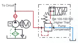
Figure 18-20 shows a normally open solenoid-operated relief valve that allows a large pressure-compensated pump to start at no load. A normally open solenoid-operated relief valve lets flow from the pressure-compensated pump go to tank until the electric drive motor is up to speed. A time delay or a flow meter with a flow switch energizes the solenoid on the relief valve to load the circuit. Deenergizing the normally open solenoid-operated relief valve unloads the pump any time to reduce power consumption, heat buildup, and noise.
Controlling a pilot-operated relief valve remotely
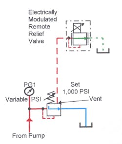
The system relief valve is normally located near the pump outlet on a typical hydraulic unit. The hydraulic unit could be at a distance from the operator, or cramped conditions could make the relief valve hard to get near. If an application’s relief pressure must change often, add a remote relief valve control to a pilot-operated relief valve for convenience.
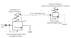
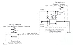
Figures 18-21 and 18-22 show a symbol for a remote relief valve setup. Figure 18-21 shows the simplified symbol; Figure 18-22 shows the complete symbol. All pilot-operated relief valves have a vent port. The vent port tees into the pilot line that connects system pressure to the direct-acting relief valve’s pilot section. The vent port tees in after the control orifice. With the vent blocked, the relief valve functions normally. With the vent open to atmosphere, the relief valve opens at the pressure of the internal main poppet or piston spring. This is usually between 20 and 70 psi. Figure 18-21 shows a small, direct-acting relief valve piped to the vent port of a pilot-operated relief valve. The small direct-acting relief functions the same as the pilot-valve section on the main relief. An operator can use the remote relief to adjust main system pressure from any convenient location within 10 to15 feet of the system relief valve.
To adjust a circuit with a remote relief valve, use the following procedure. First, set the main relief at minimum pressure and the remote relief at maximum pressure. Start the pump and check for obvious leaks and incorrect plumbing. Pressure is low during this part of the procedure. Next, slowly raise the main relief to maximum system pressure and lock it. Now, use the remote relief to set pressure to any setting less than the main relief. The operator can only adjust pressure to a level lower than the main relief setting. This is an important safety factor because it eliminates damage or injury from excess pressure caused by an inexperienced operator.
Most manufacturers recommend that the remote valve be located a maximum of 10 to 15 feet from the main relief. The greater the distance between the remote and main relief, the longer the response time of the main relief. An increase in response time allows higher pressure override, causing pressure spikes. Pressure spikes may cause premature pump, piping, or valve failure.
With a solenoid or manual valve to select more than one remote relief, it is easy to select multiple preset pressures.
Multi-pressure relief valves
Pilot-operated relief valves have a vent port. In Figures 18-21 and 18-22, the vent port is piped to a single, remote direct-acting relief for adjusting pressure remotely. Figures 18-23 through 18-25 show the vent port connected to directional valves and multiple remote reliefs. These circuits allow changes from maximum pressure to several preset or infinitely variable limits during a cycle.
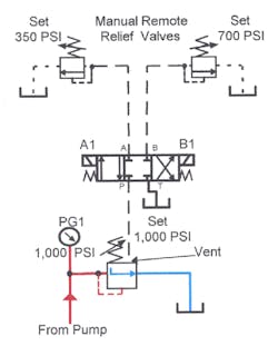
Figure 18-23 shows a pilot-operated relief valve with the vent port connected to a 3-position directional control valve. With the directional valve centered, it blocks the vent port on the relief to keep system pressure at the setting of the main relief. An open-center directional valve would vent the main relief, lowering pressure to a 20- to 70-psi range.
Some manufacturers offer a relief valve with the remote pilot heads and solenoid valve built into the valve body. This eliminates external piping but is less flexible than piping the vent of a standard pilot-operated relief valve to standard directional valves.
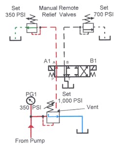
In Figure 18-24, solenoid A1 is energized. This connects the vent to the left remote direct-acting relief, dropping system pressure to a maximum of 350 psi. Energizing solenoid A1 keeps pressure from going above the setting of the left direct-acting relief. The main relief valve always limits maximum system pressure.
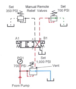
Figure 18-25 shows solenoid A1 energized, allowing system pressure to go to 700 psi. In this condition the right remote direct-acting relief controls system pressure. Set remote reliefs at any pressure lower than the main relief valve.
Figure 18-26 shows a pilot-operated relief controlled by an infinitely variable proportional or servovalve. Using a variable-flow valve to control a pilot-operated relief valve gives infinitely variable pressure. The control signal may come from a rheostat, a programmable controller, or a computer.
Purchase an infinitely variable relief valve as an assembled unit or pipe one remotely. In each case, the pilot head relief controls maximum pressure, while the servo or proportional valve only sets a lower pressure.
Unloading relief valves
An accumulator circuit using a fixed-displacement pump must have some way to unload the pump after reaching maximum pressure. A normally open solenoid-operated relief valve controlled by a pressure switch is one way to unload a pump. Chapter 1 shows this circuit and explains its operation.
Some accumulator circuits use a special type valve called an unloading relief valve. This relief valve eliminates the need for electrical, high and low pressure switches and a solenoid-operated dump valve to unload the pump. Only a few manufacturers make an unloading relief valve. Two of these operate at preset pressure differentials and may not be suitable for some accumulator circuits. One manufacture makes an unloading relief valve with adjustable pressure differentials.
Several companies make a relief unload-and-dump valve combination with other features. Operation is the same as an unloading relief valve but includes a back-flow check valve and an accumulator dump valve in the same body. See Chapter 1, Figure 44, for an explanation of this accumulator unload and dump valve.
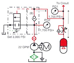
Figures 18-27 through 18-30 schematically depict an unloading relief valve in an accumulator circuit. Figure 18-27 shows the circuit after the pump starts. Normally closed relief valve A forces fluid to the accumulator and the circuit. Pressure increases as fast as the pump fills the accumulator. When the accumulator and circuit reach set pressure of 3000 psi, pilot pressure opens relief valve A and unloads the pump to tank.
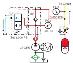
In Figure 18-28, the accumulator is at pressure and the pump is unloading. The relief valve is fully open or vented because the control piston pushes the pilot control piston off its seat. Without a control piston, relief valves relieve excess pump flow at set pressure, generating a lot of heat. This unloading relief valve has a preset differential of 15% between unloading and reloading the pump.
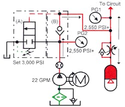
When system pressure drops to approximately 2550 psi, as in Figure 18-29, its spring force reseats the pilot control poppet again. This forces pump flow into the circuit. This action repeats as long as the pump runs. With a tight circuit and the machine not cycling, the pump unloads approximately 80% of the time.
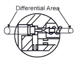
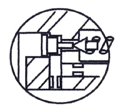
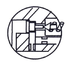
Figure 18-31 shows a cutaway view of an unloading relief valve. It is similar to a standard relief valve but has an extra control piston in its head. There is an approximate 15% difference in the area of the control piston and the pilot-control poppet seat. As pressure builds, it pushes against both sides of the control piston and against the pilot-control poppet. Nothing moves until pressure starts to force the pilot-control poppet off its seat, as in Figure 18-32. Pressure drop in front of the control piston lets it move and force the pilot-control poppet completely off its seat, Figure 18-33. Forcing the pilot-control poppet off its seat unloads the pump at 20 to 70 psi. The pilot-control poppet stays open until system pressure drops approximately 15%, then closes to force pump flow into the circuit again. When pressure rises to maximum, the pilot-control poppet is pushed off its seat and unloads the pump. This action continues anytime the pump runs.
