Sequence Valves
There are times when two or more cylinders need to stroke in a planned sequence. With two or more cylinders controlled by a single directional valve, the cylinder with the lowest resistance always strokes first. If the actuator with the least resistance is first in the sequence, the circuit runs smoothly without other valving.
When the cylinder that must move first has the highest resistance, a single directional control will not work. A separate directional valve for each cylinder is one way to sequence such a circuit. Energizing one solenoid extends the first cylinder. When the first cylinder contacts a limit switch, it energizes a second solenoid, causing the next cylinder to stroke. With this type of sequencing circuit, the first cylinder may lose holding power when the second directional valve shifts. It may require other valves to make sure the first cylinder generates and maintains the force required both before and during the second cylinder’s stroke.
Another way to force fluid to take the path of greatest resistance is to use a pressure-control valve called a sequence valve.
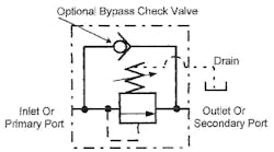
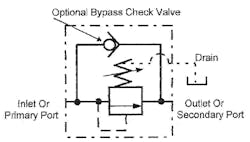
Figure 20-1 shows the schematic symbol for an internally piloted sequence valve. A sequence valve symbol is similar to a relief valve symbol. The main difference is that a sequence valve always has an external drain line — and often has a bypass check valve for reverse flow.
A sequence valve is a pressure-operated, normally closed, poppet or spool valve that opens at an adjustable set pressure. Some designs use a spring acting directly on the spool or poppet, others are pilot-operated. A sequence valve always has an external drain port to keep from trapping leakage oil. Trapped fluid modifies set pressure at best or keeps the valve from opening at worst. For reverse flow capabilities, use the integral bypass check valve shown in the symbol.
Sequence valves may be internally pilot-operated as in Figure 20-1.This is the standard arrangement for the pilot source. Fluid at the inlet port of the valve cannot pass to the secondary circuit or outlet port, until reaching set pressure. Upon reaching set pressure, the valve opens enough to let excess pump flow pass on to the second operation.
The primary circuit never drops below the sequence valve setting as long as the primary pressure is equal to or greater than the sequence pressure setting. Pressure at the outlet port of the sequence valve is that required to overcome resistance in the secondary circuit when it is not above relief valve or pressure compensator setting.
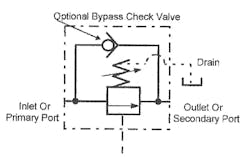
Figure 20-2 pictures the symbol for an externally piloted sequence valve. In some circuits the pilot signal to open the valve is from a source other than the line feeding it. An external pilot-operated sequence valve opens and allows flow when a remote operation reaches a certain pressure.
Sequence valves produce heat in a hydraulic system. With a pressure setting of 800 psi and resistance in the secondary circuit of 150 psi, there is a 650-psi pressure drop across the valve. This pressure drop results in heat, because its energy does not do useful work. Most sequence circuits require a heat exchanger, especially when they cycle rapidly.
Many older machines use sequence circuits because at the time they were designed there was a lack of understanding of electrical controls. Sequence circuits are unreliable and difficult to set up and maintain. Some older circuits have one directional valve and up to six sequence valves. With this many adjustments to make, it is hard to keep the cycle operating consistently.
Another potential problem with a sequence valve circuit is that actuator position cannot be assured. When a sequence valve shifts, the only sure thing is that pressure has reached a certain level. Pressure build up could be from a damaged or stalled cylinder or a kinked line. When it is necessary to positively locate an actuator, always use a limit switch or limit valve. When it is only necessary to know that pressure has built, a sequence valve in the line keeps fluid from the next action until the limit switch is contacted and pressure increases.
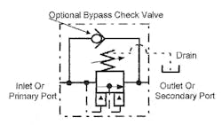
Figure 20-3 shows the symbol for a kick-down sequence valve. Its operation is different from a normal sequence valve. After a kick-down sequence valve reaches set pressure, flow passes through unrestricted. Pressure may have to reach 900 psi before flow passes through the valve, but when it starts passing, a kick-down sequence opens fully. A pressure drop of more than 50 psi across a kick-down sequence valve keeps it full open. (Note that a kick-down sequence valve causes less heat generation, but does not hold pressure on the primary circuit.)
Figures 20-14 through 20-17 show a circuit using a kick-down sequence valve operating two cylinders. A pilot-operated check valve, added to the inlet of the first cylinder, maintains pressure on the first cylinder while the second cylinder strokes at low pressure.
Another use for a kick-down sequence is unloading a pump after the circuit reaches maximum pressure. A kick-down sequence valve keeps unloading the pump until pressure drop across it falls below 50 psi. (See further explanation in conjunction with Figures 20-23.)
When using flow controls with sequence circuits, meter-in flow control is the only workable option. Chapter 10 covering flow controls, explains the reasons for this.
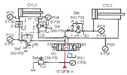
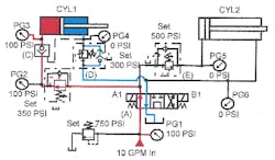
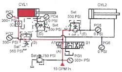
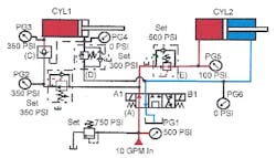
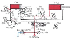
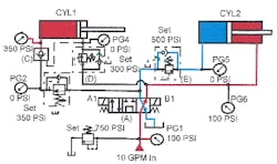
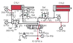
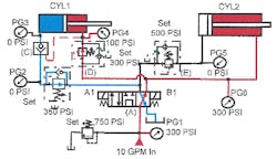
Figures 20-4 through 20-11 provide schematic drawings for a two-cylinder sequence circuit. One 4-way directional control valve controls both cylinders. The sequence is: cylinder1 extend, cylinder 2 extend, cylinder 2 retract, and cylinder 1 retract. Cylinder 2 will not extend until pressure at cylinder 1 reaches 600 psi.
A good feature of a sequence circuit: if cylinder 1 is a clamp, it does not matter how thick the part is. Cylinder 2 will not extend until cylinder 1 securely clamps any thickness part. On the other hand, if the clamp cylinder locks up for any reason before contacting the part, pressure will build and allow cylinder 2 to cycle. Any sequence circuit may fail to operate correctly at any time because of outside influences.
Two-cylinder sequence circuit
Figure 20-4 shows a two-cylinder sequence circuit at rest. The schematic drawing notes the valve pressure settings. Gauges are placed to show working pressures as the sequence progresses.
In Figure 20-5, solenoid A1 is energized and CYL1 is extending. Pressure on gauges PG1-2 and 3 show the pressure required (100 psi) to move CYL1. Even if CYL2 required only 25 psi to move, sequence valve E keeps fluid from it. CYL1 extends until it contacts a part.
When CYL1 makes part contact, Figure 20-6, system pressure increases rapidly. As pressure passes through 300 psi (as seen on gauges PG1, 2, and 3), CYL2 is still stationary. Pressure continues to climb at CYL1 until it reaches 350 psi. When pressure is 350 psi at CYL1, reducing valve (B) shuts and holds. Pressure in the rest of the circuit continues to climb until it reaches 500 psi.
When pressure reaches 500 psi, as shown in Figure 20-7, sequence valve Eopens enough to let excess pump fluid flow to CYL2. If pressure at CYL1 drops for any reason, sequence valve E shuts enough to keep system pressure at 500 psi or higher if possible. Now gauge PG1 reads 500 psi while gauges PG2 and 3 read 350 psi, and gauge PG5reads whatever it takes to move CYL2. Pressure at CYL2 changes with load variations.
When pressure on CYL2 is less than 500 psi, the pressure drop across sequence valve (E)generates heat. When pressure on CYL2goes higher than 500 psi, there is no energy loss, hence no heat. Because of reducing valve (B), pressure at CYL1 stays at 350 psi no matter how high system pressure climbs.
When CYL2 bottoms out, as in Figure 20-8, pressure at gauges PG1 and PG5 goes to 750 psi and the system relief valve starts dumping fluid to tank. Pressure at CYL1 stays at 350 psi because reducing valve (B) will not let it go higher. Reducing valve (B) prevents CYL1 from crushing the part while CYL2 does its work.
Energizing solenoid B1 on directional valve (A) , Figure 20-9, starts returning the cylinders to their at-rest positions. In this circuit, CYL2 retracts first, while CYL1 holds under pressure when the directional valve shifts. Pilot-operated check valve (C) traps oil in the cap end of CYL1 — note gauge PG3 — so it does not relax and release the part. Oil now goes to CYL2 and sequence valve (D) . CYL2 retracts first because it only takes 100 psi to move it, while the pressure setting at sequence valve (D) is 300 psi. Pressure at CYL2 changes as it retracts, but never goes higher than 200 to 250 psi.
When CYL2 fully retracts, system pressure increases rapidly, as seen in Figure 20-10. Pressure in the rod end of CYL2 finally increases to 300 psi. CYL1 still has approximately 350 psi in its cap end due to pilot-operated check valve (C) . (Pressure at CYL1 may drop due to leaks at seals or piping with the circuit described here.) With a short cycle time, pressure drop is minimal. If decreasing pressure is a problem, tee a small accumulator in the line between pilot-operated check valve (C) and the cylinder. See a leakage make-up circuit using an accumulator in Chapter 1, Figures 1-24 to 1-27.
When pressure reaches 300 psi in Figure 20-11, CYL1 starts to retract. Because of sequence valve (D) , pressure at the rod end of CYL2 stays at 300 psi. When oil passes through sequence valve (D) , it first sends a pilot signal to open pilot-operated check valve (C) . After valve (C) opens, CYL1 can retract. Pressure at the rod end of CYL1 is whatever it takes to stroke the cylinder home.
Simple sequence circuit using modular valves
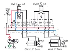
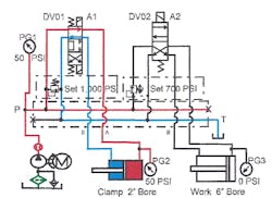
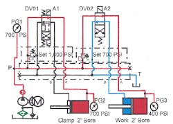
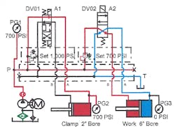
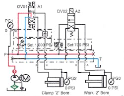
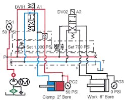
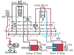
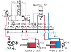
Figures 20-12 through 20-15 show a modular or sandwich-type sequence valve in a circuit. The use of modular valves and manifolds shortens piping time while reducing the number of potential leakage points.
Figure 20-12 pictures the system at rest. A fixed-displacement pump, unloading at no pressure through a tandem-center valve, is the power source. This circuit has some heat generation but makes sure the Clamp cylinder never goes below a certain pressure while the Work cylinder extends and retracts. Also, the Work cylinder cannot even try to extend until CYL1 makes a limit switch.
In Figure 20-13, solenoid A1 on directional valve DV01 is energized. Pump flow goes to the Clamp cylinder, extending it to the work. Because this requires only low pressure and uses all the pump flow, there is no heat generation.
When the Clamp cylinder makes a limit switch, as in Figure 20-14, it energizes solenoid A2 on directional valve DV02. The modular sequence valve under DV02 assures that the Clamp cylinder sees at least 700 psi before the Work cylinder extends. If the Work cylinder only requires 450 psi to extend, the 300-psi energy loss generates heat. With this sequence circuit, Clamp cylinder pressure cannot drop below 700 psi while the Work cylinder strokes. Directional valve DV02, shifted by a limit switch, ensures that the Clamp cylinder contacts the part before the Work cylinder cycles.
To retract the Work cylinder, deenergize solenoid A2 as in Figure 20-15. This directs oil from the pump to the rod end of the Work cylinder. The Clamp cylinder still has 700 psi on it to hold the part firmly while the Work cylinder returns home.
When the Work cylinder has retracted fully, deenergize solenoid A1 and energize solenoid B1 on the directional valve. The Clamp cylinder returns, DV01 deenergizes, and the cycle ends.
Adding more directional valves like DV02 and more modular sequence valves will ensure the proper pressure for more working functions. A single screw-in cartridge sequence valve — added to the bar manifold in the pump line between the clamp valve and the working cylinder valves — can eliminate multiple sequence valves. The extra cost of special manifolds for this arrangement is a good investment.
Sequence circuit with kick-down sequence valve
Figures 20-16 through 20-19 show a kick-down sequence valve in place of the standard sequence valve. With a kick-down sequence valve, add the modular pilot-operated check valve shown in the cap-end line of the Clamp cylinder. A pilot-operated check valve blocks pressurized fluid in the cap end of the clamp cylinder when the kick-down sequence valve opens.
In Figure 20-17, solenoid A1 on directional valve DV01 is energized. Pump flow goes to the Clamp cylinder through the pilot-operated check valve to extend the Clamp cylinder. Because this takes low pressure and all pump flow, there is no heat generation.
After the work is contacted, Figure 20-18, energize solenoid A2 on directional valve DV02. The modular kick-down sequence valve under DV02 causes 700-psi pressure to build in the Clamp cylinder before the Work cylinder extends. If the Work cylinder only requires 450 psi to advance to the work, system pressure drops to 450 psi with minimal heating.
The Clamp cylinder maintains force because the modular pilot-operated check traps 700-psi fluid in it. With a short cycle time, pressure drop is minimal. If decreasing pressure is a problem, tee a small accumulator in the line between the manifold and the cylinder's cap-end line. See a leakage make up circuit using an accumulator in Chapter 1, Figures 1-24 to 1-27.
To retract the Work cylinder, deenergize solenoid A2 as in Figure 20-19. This sends pump flow to the rod end of the Workcylinder. The pilot-operated check still maintains 700 psi or higher on the Clamp cylinder, holding the work firmly while the Work cylinder retracts.
After the Work cylinder retracts fully, deenergize solenoid A1 and energize solenoid B1 on the directional valve, retracting the Clamp cylinder to its home position. Pilot pressure from port B opens the pilot-operated check valve, allowing trapped fluid to leave the cap end of the Clamp cylinder. After the Clamp cylinder returns, DV01 deenergizes and the cycle ends.
Pump unloading with kick-down sequence valve
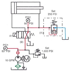
Figures 20-20 through 20-23 show a kick-down sequence valve automatically unloading a pump at the end of a cycle. The kick-down sequence valve and a single-solenoid directional valve can replace an open- or tandem- center, 3-position valve unloading circuit. This circuit simplifies the electrical controls because it only uses one solenoid.
A punch cylinder application, using a single-solenoid, two-position, spring-return valve and a fixed-displacement pump could operate this way with little heat generation. Figure 20-20 shows the circuit at rest. The pump, unloading through kick-down sequence valve (A) at about 50 psi, is ready for a cycle.
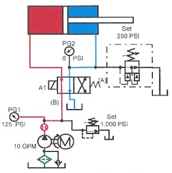
Energizing solenoid A1 on directional valve (B), Figure 20-21, directs oil to the cap end of the punch cylinder. The cylinder extends at the pressure required to move it. Oil from the rod end of the cylinder flows freely to tank, greatly reducing pressure in this line. The pressure drop allows kick-down sequence valve (A) to close (or reset) for the retract cycle.
The cylinder extends until it meets the part. Pressure builds until the punch goes through the part. A limit switch then deenergizes solenoid A1 on directional valve (B) . Directional valve (B) spring returns to normal and cylinder travel reverses and retracts.
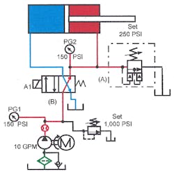
The cylinder retracts at the pressure required to move it, Figure 20-22. Kick-down sequence valve (A) stays closed because its setting is higher than the pressure retracting the cylinder. The cylinder retracts until the end of stroke or until it contacts a dead stop.
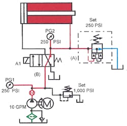
When the retracting cylinder stops, Figure 20-23, pressure builds in its rod end. When pressure reaches the setting of kick-down sequence valve (A) , the valve opens and unloads the pump to tank at approximately 50 psi. The circuit has returned to the conditions of Figure 20-20.
A kick-down sequence valve is a unique component that can simplify the electrical control of systems with one or two cylinders. At the same time, there is minimal energy loss and heat generation.
CAUTION: When using any pressure-control valve, the only thing certain when they operate is that they have reached set pressure.
Pressure-compensated pump with self-adjusting overpressure relief valve
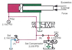
Some designers use a relief valve with a pressure-compensated pump to reduce pressure spikes as the pump rapidly goes from full flow to no flow. Figure 1-16 in Chapter 1 shows and explains a circuit using a pressure-compensated pump and a relief valve. Figures 1-17 to 1-19 show another circuit using an accumulator to protect the pump. The accumulator circuit almost eliminates pressure spikes — plus it gives faster actuator response at the start of a cycle. However, there are pressure-compensated pump circuits that need overpressure protection that an accumulator may not be capable of providing alone. The schematic diagrams in Figures 20-20 through 20-24 show a circuit with a cylinder opposed by a greater force than its pressure capabilities. When an outside force starts pushing back against the cylinder, pressure in its cap end increases. Without a relief valve in the circuit, pressure might easily exceed the rating of the valves, piping, pump, and cylinder. This happens because a pressure-compensated pump compensates to no flow at set pressure, but will not allow reverse flow to relieve pressure above its setting.
Relief valve (A), installed anywhere in the pressure line, protects the system when set 150 to 200 psi higher than the pump compensator. The inlet to a pressure-compensated pump should never see a pressure higher than its compensator setting. Adding check valve (B) at the pump outlet assures that pressure at the pump never goes above the compensator setting. However, relief valve (D) may cause problems, as stated in Chapter 1, page ACC7. Figures 20-25 through 20-27 show an overpressure protection circuit that is less prone to problems.
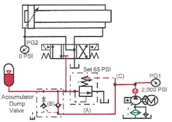
Figure 20-25 shows internally piloted, externally drained, low-pressure sequence valve (A) teed into the pump outlet. (Valve (A) has a low-pressure spring rate between 50 and 250 psi.) The outlet of sequence valve (A) goes directly to tank. Isolation check valve (B) in the pump outlet line before the sequence valve keeps reverse flow and excess pressure away from the pump. Pilot line (C) from the pump outlet before check valve (B) goes to the external drain port of sequence valve (A).
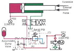
With the circuit at rest and the pump running, system pressure is the pump compensator setting. Pump pressure at the internal pilot is trying to open sequence valve (A), but at the same time holding it closed through the external drain port. With a sequence-valve spring setting of 65 psi, it will not open to tank until pressure after check valve (B)goes at least 65 psi higher than pump compensator setting, as in Figure 20-26.
The main reason this overpressure relieving circuit is better than a circuit with a standard relief valve is that adjusting the pump compensator not only changes system pressure, but also automatically raises relief pressure. The pump never relieves to tank and the circuit always relieves when pressure in it increases more than the sequence-valve spring setting.
With this overpressure circuit there is no protection from pressure spikes when the pump compensator has to work quickly. Using the accumulator shown in the schematic diagrams protects the pump when it has to compensate rapidly. The accumulator also makes the circuit more responsive at cycle start.
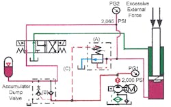
This sequence-valve relief works anywhere in the circuit to protect any line from overpressure. Figure 20-27 shows a sequence valve teed into the cap end line of a cylinder with excess external force. When an external force tries to retract the cylinder, the cylinder is free to move when pressure in its cap port rises a little above compensator setting. Any other time the sequence valve stays closed because its inlet never sees pressure higher than compensator setting.
