High-efficiency circuit operates 100-ton trim press
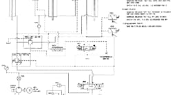
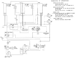
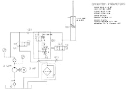
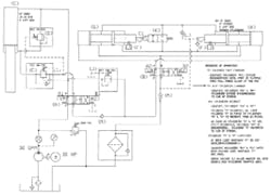
Figure 23-1 is a schematic circuit diagram for a 100-ton trim press, shown at rest with the pump running. This press has a 24-in. total stroke with a 1.0-in. high-tonnage stroke. It completes a dry cycle in about 10 seconds.
Pump PUMP01 is rated at 13 gpm. Its compensator is set at approximately 3000 psi. Output from the pump flows through flow meter FM01 to directional valve DV01, which has ports "P," "B," and "T" connected in center position. From there, fluid flows to backpressure check valve CK02 and 3-micron filter RF01. Pressure at gauge PG01 holds between 75 and 100 psi with the press at rest, providing ample pilot pressure for directional valve DV01.
Port "A" on directional valve DV01 connects to the cap ends of two 3.25-in. bore double-acting cylinders CYL01 and the extend side of double-rod end cylinder CYL02. The rod sides of these cylinders connect to port "B" on the directional valve.
Directional valve DV02 supplies pilot pressure to sequence valve SEQ01 and two pilot-operated check valves POCK01 for cylinder regeneration during fast advance. Directional valve DV02 also decompresses the cylinders before retracting.
Externally piloted sequence valve SEQ01 connects the cap and rod ports of the 3.25-in. bore cylinders in a regeneration circuit for a fast advance stroke.
Check valves POCK01 allow oil to flow from one end of the double-rod end cylinder to the other during fast advance and retract. Shuttle valve SV01 directs pilot pressure to the pilot-operated check valves from two sources.
Counterbalance valve CB01 holds the platen in position at rest, and keeps it from running away during the high-tonnage advance stroke. (Because it has an external pilot, set it one time for all platen and tooling weights.) External piloting also eliminates all cylinder rod-end backpressure during the high-tonnage portion of the cycle.
Check valve CK01 allows oil out of double-rod end cylinder CYL02 during the high-tonnage stroke, but prevents flow from entering it as the platen retracts.
Pressure switch PS01 ends the pressing cycle at a set tonnage. After the pressing cycle is completed, pressure switch PS02 keeps directional valve DV01 from shifting until the cylinders decompress.
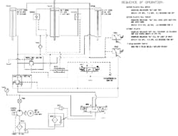
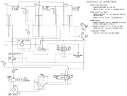
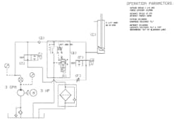
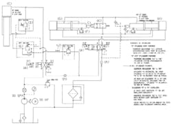
Platen extending rapidly — Energizing solenoid A1 on directional valve DV01 and solenoid A2 on directional valve DV02 moves the cylinders to the positions shown in Figure 23-2.
Pump flow goes to the cap ends of cylinders CYL01 and they begin to extend. At the same time, pilot pressure opens sequence valve SEQ01 and pilot-operated check valves POCK01. Oil now regenerates from the rod ends of the 3.25-in.-diameter cylinders through SEQ01 to their cap ends for high speed at low volume. Oil in the bottom of CYL02 transfers to the top, keeping it full, ready for high-tonnage pressing.
The pressure setting of counterbalance valve CB01 is high enough to make sure oil regenerates during this portion of the cycle, but low enough not to waste energy after regeneration is disabled. (About 400 psi works well on presses in this type of service.)
The platen extends at approximately 7.5 ips for about 3.1 sec. to produce 23 in. of travel.
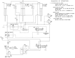
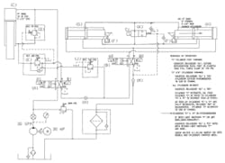
Platen at full tonnage — A limit switch or encoder indicates that the platen is in close proximity to the part and the circuit shifts as shown in Figure 23-3.
Solenoid A1 on directional valve DV01 stays energized, but solenoid A2 on DV02 deenergizes.
Now sequence valve SEQ01 and pilot-operated check valves POCK01 close. The 3.25-in.-diameter cylinders no longer regenerate, so forward speed slows.
The double-rod end cylinder can still transfer fluid through the pilot-operated check valves so the platen does not slow to pressing speed until it contacts the work. Counterbalance valve CB01 opens during the slow-down part of the cycle, letting fluid go to tank, but not allowing the platen to run away.
At contact with the work, pilot-operated check valves POCK01 close, so pump flow goes to all three cylinders. Forward speed slows to approximately 0.6 ips, so it takes about 1.75 sec. to travel 1.0 in. Force during this portion of the stroke is more than 237,000 lb at 3000 psi.
Externally piloted counterbalance valve CB01 opens fully during the trimming part of the cycle to eliminate all backpressure on the cylinders.
During part trim, oil from the bottom of the double-rod end cylinder flows to tank through check valve CK01 and counterbalance valve CB01 along with fluid from the other two cylinders.
When pressure reaches the setting on pressure switch PS01, directional valve DV01 deenergizes to unload the pump and set up for decompression.
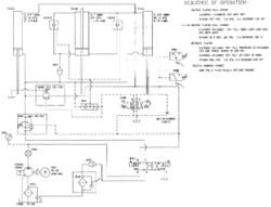
Cylinders decompressing — At the end of the high-pressure trim cycle, there may be a lot of stored energy in the cylinders and piping. (Also, if the tie rods on the press stretch, more energy is stored.) If directional valve DV01 shifts immediately to retract the cylinders, stored energy would send oil to tank with enough velocity and force to damage pipes and valves. In a short time, shock damage to plumbing and components could make the machine inefficient and messy.
To avoid this, after trimming the part, the circuit changes as shown in Figure 23-4. Directional valve DV01 centers to unload the pump and block oil in the cylinders' cap ends. Energizing solenoid B2 on directional valve DV02 opens a controlled flow path from the cap end of the cylinders to tank. Stored energy dissipates rapidly through this path to tank without decompression shock.
This adds time to the overall cycle, but greatly increases machine life and reliability. (Always figure in the added time of decompression when designing a circuit with stored energy.) Decompression can take from 0.25 to 2.00 sec., depending on fluid volume and pressure. Offset the added cycle time with a faster cylinder stroke.
When pressure in the cap-end line of the cylinders reaches approximately 300 psi, pressure switch PS02 energizes solenoid B1 of directional valve DV01 to retract the platen.
Platen retracting at high speed — After the cylinders decompress, solenoid B1 on directional valve DV01 energizes as shown in Figure 23-5. Pump flow goes to the rod ends of 3.25-in.-diameter cylinders CYL01 through the bypass check valve on counterbalance valve CB01 to retract the platen.
Check valve CK01 blocks pump flow from the bottom of double-rod end cylinder CYL02 during the retract cycle.
Pilot oil from the cylinder rod end line opens pilot-operated check valves POCK01 through shuttle valve SV01. This action opens a path for oil transfer from top to bottom of the double-rod end cylinder.
The platen retracts at a rate of approximately 4.75 ips, and travels 24 in. in about 5 sec. Oil in the double-rod end cylinder transfers from top to bottom through pilot-operated check valves POCK01 to keep it full for the next cycle.
It appears the double-rod end cylinder keeps the same fluid in it all the time -- and might overheat. In actual operation, this cylinder gets some fresh oil from the pump and sends an equal amount to tank during each cycle. If the high-force stroke of the cycle is 0.5 in., cylinder volume is replaced completely every 48 cycles.
The reason for a circuit design such as shown here is to reduce pump displacement as well as valve and piping size while maintaining a fast cycle. A conventional cylinder regeneration and hi-lo pump circuit requires approximately 70 gpm to meet the cycle time of this circuit.
Another fast-cycle option is a prefill valve and a cylinder with a 9.0-in. oversize rod. This circuit could meet or exceed the above cycle time. A prefill circuit lets the platen lower from its own weight, so the extend part of the stroke could be faster.
This schematic diagram uses several of the basic circuits shown in other parts of this manual. Refer to the appropriate sections for a refresher on different valve functions and use.
High-efficiency circuit operates increment feeder for cardboard sheets
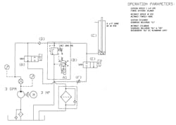
The circuit diagrammed in Figure 23-6 cycles a cylinder slowly in incremental steps as it extends, and then drops it very quickly to pick up another load. Feeding sheets of paperboard or plywood onto a conveyor is a common use for this circuit.
A small (3-gpm), fixed-displacement pump sends oil through a flow meter, normally open 2-way directional valve (A), and a filter to tank. In the condition shown in the diagram, the pump unloads to tank at almost no pressure, continually filtering all flow.
The pump can be small because it only has to extend the cylinder a short distance each feed cycle. Because pump flow is immediately available, it is always ready to raise the load.
Check valve (D) keeps cylinder fluid from going to tank while the pump unloads. This same check valve allows free flow to the cylinder when required.
Normally closed solenoid-operated relief valve (S) protects the system from excess pressure and gives a high-flow path to tank to lower the table for another load. It also decelerates the cylinder as it nears bottom and eliminates shock damage to the hydraulic components and the machine.
Normally closed 2-way directional valve (E) and needle valve (F) give a slow-down bypass to the normally closed solenoid-operated relief valve to make sure the cylinder bottoms out smoothly.
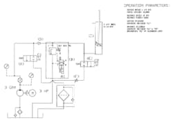
Cylinder extending — Energizing solenoid C1 on directional valve (A) sends pump flow to cylinder (C), making it extend as diagrammed in Figure 23-7. This action takes place as fast as directional valve (A) shifts because the pump is at full flow. Cylinder (A) extends at 1.50 ips at a maximum force of 10,000 lb, as long as solenoid C1 stays energized.
If the cylinder meets a resistance that calls for more than 1500 psi, pump flow goes to tank through normally closed solenoid-operated relief valve (B) and the cylinder stalls.
Solenoid C1 shifts as often as necessary to raise the load.
When the table gets all the way up, a limit switch signals the control circuit to lower for another load.
Cylinder retracting at high speed — To lower the table fast, the valves shift as shown in Figure 23-8.
Solenoid A1 on normally closed solenoid-operated relief valve (S) energizes to vent it. This allows the valve to open with about 20-psi backpressure. The 0.75-in. valve in this circuit passes about 30 gpm at 20- to 30-psi pressure drop, so the cylinder retracts rapidly from machine weight. On this particular machine, the weight gave it a speed of approximately 12 ips or about a 5-sec lowering time. Increasing load-induced pressure on the cylinder would make it even faster.
The solenoid on normally closed 2-way valve (E) also energizes during fast retract of the cylinder. It does not add much speed because its function is to let the cylinder descend slowly through the last 0.5 to 1.5 in. of travel. (Set the slow-down limit switch high enough to decelerate the cylinder before it hits bottom.) Fluid viscosity or weight changes give more or less flow to increase or decrease the slow-down distance.
Retracting cylinder slows down — The circuit in Figure 23-9 shows the valve positions as the retracting cylinder nears the end of stroke and makes the slow-down limit switch.
All solenoids are deenergized except C2 on normally closed 2-way (E). When solenoid A1 on normally closed solenoid-operated relief valve (S) deenergizes, the valve starts to close. When this happens, pressure from the load and high -flowing fluid builds to relief setting. The relief valve resists flow but does not close completely all at once (like a directional valve would). Backpressure at the cylinder causes it to decelerate smoothly and quickly with little or no shock.
With relief pressure set low, deceleration takes longer. With relief pressure set high, deceleration is quicker. In any event, cylinder slowing does not consistently stay the same.
Always position the slow-down limit far enough from end of stroke to decelerate the cylinder before it reaches bottom. This means it could stop before bottoming out when the only control is normally closed solenoid-operated relief valve (S).
Normally closed 2-way valve (E) provides another controllable flow path around the normally closed solenoid-operated relief valve. Set needle valve (F) to let the cylinder move quickly, but not fast enough to shock the machine when it reaches bottom. Use a cylinder cap-end cushion as a final shock absorber to shorten slow-down travel.
The slow-down part of the stroke is usually less than 2 in., so it poses no time problem.
After the cylinder bottoms out, solenoid (C2) on normally closed directional valve (E) deenergizes, ending the cycle.
Opposing trim cylinders with synchronous movement
Two cutter heads, driven by opposing cylinders, must meet near perfectly in center regardless of differing loads. If the cylinders are out of phase, parts can be damaged and the profiled cutters may break.
An original circuit used two pumps and directional valves to synchronize the cylinders. The machine was useable but parts often were under par and cutting tools had to be changed frequently.
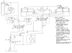
The schematic diagram in Figure 23-10 shows the new circuit now on the machine. Now the cutters move almost perfectly in unison, and produce a better part with no tooling damage.
A single 30-gpm pump replaced two 21-gpm pumps with a cycle time decrease of 1.5 seconds.
Clamp cylinder (C) has an oversize rod and uses a regeneration circuit for fast, low-volume extension. Counterbalance valve (E) keeps the vertical clamp cylinder from running away. Sequence valve (J) assures that the part stays tightly clamped as trim cylinders (G) and (H) advance to the work.
Both directional valves (A) and (B) have pump-to-tank center conditions, so the pump unloads until they shift.
Check valve (N) prevents backflow to the clamp cylinder's rod end while the trim cylinders work.
Check valve (M) provides backpressure to supply pilot oil to both solenoid pilot-operated directional valves and makeup fluid to the tandem cylinders.
Two check valves (L) allow fluid into the double-rod end cylinder's trapped area to make up for leakage. Pressure here also keeps the seals energized to reduce leaks.
Normally closed 2-way directional valve (K) re-synchronizes the trim cylinders if they get out of phase. It operates automatically any time limit switches (F) do not make simultaneously.
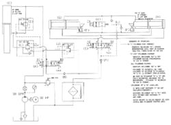
Clamp cylinder (C) extending in regeneration — Energizing solenoid A1 on directional valve (A) starts clamp cylinder (C) forward, as seen in Figure 23-11. Oil from the rod end of cylinder (C) regenerates to the cap end and almost doubles its speed. (Because the cylinder needs minimum force to move to the part, a regeneration circuit such as this works well and uses a smaller pump.)
Set counterbalance valve (E) high enough to force rod end oil to regenerate through sequence valve (0) until the cylinder meets the work.
Clamp cylinder (C) advances at fast speed until it contacts the work. At work contact, pressure increases and opens counterbalance valve (E). This action drops backpressure on the rod end of cylinder (C), giving full force to clamp the part. When valve (E) opens, sequence valve (O) closes, shutting off the regeneration path.
Pressure must climb to 750 psi before oil can pass sequence valve (J) and flow on to trim cylinder valve (B). Sequence valve (J) makes sure the part has ample clamp force while the trim cylinders advance to the work. Pressure in clamp cylinder (C) never drops below 750 psi if sequence valve (J) is set correctly.
Cylinder (C) extended at full force, cylinders (G) and (H) extending in synchronization — After clamping the part, energize solenoid A2 on directional valve (B) as shown in Figure 23-12. Sequence valve (J) maintains 750 psi at the clamp cylinder but allows pump flow to go to the trim cylinders.
Trim cylinders (G) and (H) now advance in synchronization. They stroke together regardless of load difference until both cylinders stall at relief pressure. The reason trim cylinders (G) and (H) stay together is that oil from each of the double-rod end cylinders transfers to its opposing cylinder's opposite end. If one cylinder moves an inch, it is only because the opposing cylinder also moved that distance. If one cylinder needs to develop more force, energy from the opposing cylinder transfers to it. Neither cylinder stalls until resistance against it is greater than both cylinders can overcome.
In case of leakage from the double-rod end cylinders, backpressure check valve (M) forces pump fluid into the trapped area through check valves (L).
Except for piston or rod seal bypass, the trim cylinders always stay synchronized. In case they do get out of phase, normally closed 2-way directional valve (K) allows them to re-synchronize.
All cylinders retracting — After trimming the part, the valves shift to the positions shown in the schematic diagram in Figure 23-13. Energizing solenoids B1 and B2 on directional valves (A) and (B) directs pump flow to the rod end of cylinder (C). Pump flow goes around the bypass check in counterbalance valve (E) to the cylinder's rod end. Sequence valve (O) is held closed by its light spring and pressure from retracting cylinder (C).
Oil from the cap end of cylinder (C) goes through directional valve (A), check valve (N), and directional valve (B) to the rod ends of cylinders (G) and (H). The pump only has to retract cylinder (C). Return flow from cylinder (C) retracts the trim cylinders. This is possible because cylinder (C) has more than enough oil to fill the rod ends of the trim cylinders at the low force required to retract them.
All three cylinders continue retracting quickly because cylinder (C) has an oversize rod. When trim cylinders (G) and (H) bottom out, solenoid B2 on directional valve (B) deenergizes so clamp cylinder (C) can complete its retraction stroke.
When cylinder (C) bottoms out, the limit switch indicates the end of the cycle and deenergizes solenoid B1 on directional valve (A). Now the pump unloads because the circuit is back to the "At rest with pump running" condition.
Cylinders (G) and (H) stay synchronized because they must both make their limit switches (F) before directional valve (B) centers.
Cylinders (G) and (H) re-synchronizing — During each cycle, trim cylinders (G) and (H) return to make limit switches (F). If one limit switch makes first, that indicates the cylinders are out of synchronization. The schematic diagram in Figure 23-14 shows how the cylinders re-synchronize if this happens.
In the diagram, trim cylinder (H) is late making its limit switch. When this condition occurs, the control circuit automatically energizes solenoid C1 on normally closed directional valve (K). Because all cylinders are in the retract mode, pressure on the rod end of cylinder (H) keeps it retracting. It can move by itself because open directional valve (K) provides a flow path from back to front of the double-rod end cylinders during this part of the cycle.
When both limit switches (F) make, solenoid C1 on directional valve (K) deenergizes. Solenoid B2 on directional valve (B) deenergizes, letting it center, and allowing clamp cylinder (C) to keep retracting.
Because re-synchronizing is automatic, there is never a build up of stroke error, which could allow damage to cutters or parts.
