From Deformation to Calibration: Installing O-Ring Energized Piston and Rod Seals
Here’s an astonishing figure: At least 50% of seal failures in systems involving a piston, rod, or both are due to improper installation. Or perhaps it’s not that surprising, given the number of things that can go wrong.
Small seals, especially those made of engineered plastic, can be extremely difficult to install. U-shaped grooves that require kidney-beaning of seals to fit into place can be an issue, as can sharp edges that may cause nicks. Regardless of the problem, the result is the same: Improper installation leads to leaks and lost productivity.
This article details the proper installation of O-Ring energized piston and rod seals, including recommendations for preventing deformation, proper heating methods, lubrication and friction considerations, installation tools, and calibration.
An O-Ring energized seal consists of a plastic sealing jacket, most commonly of Polytetrafluoroethylene (PTFE). This provides wear resistance and friction properties but is not elastic. It therefore needs to be energized by an elastomer seal, usually an O-Ring.
There are four steps to take prior to installing any type of piston seal or rod/shaft seal:
- Ensure the bore or rod/shaft has a lead-in chamfer. If not, use a calibration sleeve.
- De-burr and chamfer sharp edges and cover the tips of screw threads.
- Remove machining residue, such as chips and dirt. Carefully clean all parts.
- Seal installation is easier if the bore or rod is oiled. Use a lubricant compatible with the seal, the O-Ring, and the application. Do not use lubricants containing solid particles.
Closed Groove Piston Seal Installation
To properly seat an O-Ring energized piston seal into a closed groove, the plastic element of the seal must be expanded. The resulting deformation leaves a diameter increase that needs to be calibrated.
Heating the seal immediately prior to expansion can facilitate this process, making calibration easier. Generally, plastic seals are heated with steam, with a hot air gun, by submersion in oil, or by submersion in water. Many plastics, such as PTFE, the material most commonly used in O-Ring energized seals, are resistant to temperatures above 200°C, but operator safety usually limits the heat used to less than 100°C.
Some plastics, such as ultra-high molecular weight polyurethane, nylon, and thermoplastic polyurethane, though, should not be heated to above 80°C, and others not exposed to hot water or steam. This should be checked before installation. After heating and installation, thermal contraction of the plastic element of the seal during cooling assists in bringing the jacket back to the correct diameter.
When a high amount of friction is present during installation, lubrication of both the jacket and installation tool is recommended. The lubricant used must be compatible with both the plastic element of the seal, the O-Ring and the application. Generally, using the system fluid is preferable. Lubricants containing solid particles should never be used.
To install an O-Ring energized piston seal into a closed groove without tools, first stretch the O-Ring by applying two pieces of woven or plastic packing band. Then place the O-Ring into the piston-seal groove, ensuring it’s not twisted. Use the same method to expand the jacket, stretching it over the piston and into the groove.
To install an O-Ring energized piston seal into a closed groove with tools, first insert the O-Ring into the piston-seal groove using the method described above. Then place an installation cone over the piston and align it with the seal groove. Place the jacket and an expanding pusher in position. Then rapidly expand the seal over the installation cone and into the groove. Remove the cone and the pusher.
Using tools can reduce seal deformation. A shorter expansion time limits seal-diameter increase, facilitating seal resizing. Sharp-edged installation tools should never be used as they can nick the seal.
Split Groove Piston Seal Installation
Several factors should be considered when installing an O-Ring energized piston seal into a split groove. For seals with a flat O-Ring contact area, it’s best to place the O-Ring into the groove and press the jacket axially onto it, keeping the parts in place until the housing groove is closed. Heating the plastic element of the seal before installation, or stretching it using a cone or similar implement, can aid in proper installation.
For O-Ring energized seals with a concave O-Ring contact area, assemble the O-Ring or O-Rings inside the seal jacket, slide the assembly onto the groove, and keep the parts in place until the housing groove is closed. Again, heating the plastic element of the seal prior to installation can facilitate the process.
Calibrating Piston Seals
Calibration is necessary to ensure a piston and seal can be inserted into a cylinder without damaging the plastic element of the seal. In a closed-groove assembly, this means the jacket must be sufficiently reduced in diameter to provide uniform contact with the O-Ring. Compressing the jacket to the bore diameter usually involves a calibration sleeve and can be performed as a separate installation step or when the piston is inserted into the bore.
The latter approach requires the calibration sleeve to be designed to fit in the cylinder shell. And if used, it provides the advantage of assisting with the secure location of the piston wear rings. When a separate calibration sleeve is not available, the jacket can be calibrated directly in the cylinder bore. This, however, requires the length of the bore lead-in chamfer to be increased correspondingly. The chamfer should have a rounded edge and an angle of less than 30 deg.
The calibration sleeve should be made from a polymer material with good sliding characteristics and high surface quality—for example, Polyoxymethylene (POM) or polyamide—to avoid seal damage.
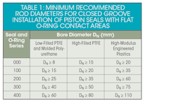
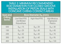
Because assembly in closed grooves is particularly demanding for small-bore diameters, we include the following recommendations for these.
Before beginning any rod or shaft seal installation, it’s important to complete the four steps outlined at the top of the article.
For assembly of an O-Ring energized seal into a split groove, place the O-Ring in the groove, press the seal jacket axially into the O-Ring, and keep the parts in place until the housing groove is closed. If the seal has a concave O-Ring contact area, it may be necessary to fold the plastic element of the seal into a kidney-bean shape during installation. Before the final assembly step of inserting the rod into the cylinder gland, elastomer-energized seals must be calibrated using a calibration mandrel or a long lead-in chamfer with a rounded edge.
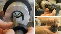
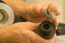
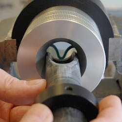
For assembly into a closed groove without installation tools, place the O-Ring into the groove; compress the jacket into a kidney shape, taking care not to have any sharp bends or a bend where there is a notch. Place the seal jacket in a compressed form into the groove and push against the O-Ring to form the seal into a ring again, and then calibrate the seal using a mandrel with a long lead-in chamfer and rounded edges.
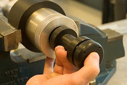
Two installation tool options are available for rod/shaft seals. For low quantities and rod diameters smaller than 30 millimeters, an inserter tube and pusher are recommended. For higher quantities, a spring-loaded, adjustable tool is recommended as it ensures repeatability in the process while reducing installation time.
Calibrating Rod/Shaft Seals Installed into Closed Grooves
Calibration ensures the rod/shaft can be inserted into the cylinder gland without damaging the seal. The seal must be concentric on the rod. Therefore, after installation in closed grooves, the folded jacket must be expanded to provide uniform contact with the O-Ring.
This can be done with a calibration mandrel or the rod. The rod can only be used on its own if the rod has a long lead-in chamfer with a rounded edge and an angle of less than 30 deg. The calibration mandrel should be made from a polymer material with good sliding characteristics (like POM or polyamide) to avoid damaging the seal. For single-acting seals, insert the calibration mandrel from the direction related to the seal profile, generally from the low-pressure side.
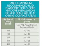
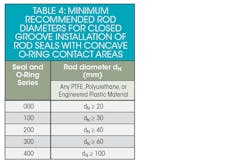
Because assembly in closed grooves is particularly demanding for small-rod diameters, we include the following recommendations for these.
Piston and rod wear rings provide significant protection against metal-to-metal contact, help centralize the piston or rod, and reduce side-loading. These are, therefore, highly recommended in piston/rod systems.
Generally, wear-ring installation is simple as wear rings are split. If a wear ring that is not split is used in a closed-groove system, its installation would be similar to the installation of a rod or piston seal as described above.
Summary and Further Recommendations
At least 50% of root-cause examinations of system breakdowns due to seal failures find that the seal was improperly installed. Thus, a high degree of attention should be paid to education. This is to ensure that unidirectional seals are not installed facing the wrong direction; potential problem areas, such as bores with sharp edges that can nick the seal during assembly, are avoided; and the need for manual or tool-based calibration to reduce the diameter of a seal stretched during installation are eliminated.
The best resource for information on whether an installation tool would speed installation and/or prevent seal damage is your seal supplier. The same is true for troubleshooting installation issues. The seal supplier is likely to have experience with such issues and know how to remediate them.
Finally, although seal suppliers recommend a highly-controlled environment for seal installation, this is extremely difficult to achieve in the field. Designers should consider the likelihood a damaged seal will need to be uninstalled and a new one installed in less-than-ideal conditions.
In many cases, the seal supplier can recommend a seal that’s either easier to install or is more durable, reducing the chance that seal damage will cause system failure. In addition, if the seal supplier is involved from application concept, it may be possible to design out potential installation issues.
Beth Figliulo is fluid power segment manager and Michael Cook is fluid power technical specialist at Trelleborg Sealing Solutions.
About the Author
Beth Figliulo
Fluid Power Segment Manager
Michael Cook
Fluid Power Technical Specialist, Trelleborg Sealing Solutions

Leaders relevant to this article:
