Test Results Compare Buffer Seals for Hydraulic Cylinders
Click here for Part 1 of this series.
At a Glance:
- Testing determines which factors affect buffer seal performance.
- The wrong seal in an application can be damaged.
- It is critical that designers check out their applications’ operating parameters before selecting a buffer seal.
To examine and compare the two most common types of buffer seals—high-sealability and friction optimized seals—and the parameters that extend their service lives, engineers developed a test rig that covers all application parameters to get an overview on seal performance.
What was learned during these investigations should help engineers understand the seal types and the interactions between seals so they can better specify the most appropriate ones for their applications.
Gathering Data
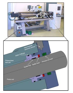
The test-rig consisted of a pressurized test cell, a piston rod, an electrical drive and a hydraulic pressurizer. The hydraulic oil had a viscosity class of 46. An additional pressure sensor was installed between buffer and primary rod seals to investigate possible intermediate pressures.
Test Protocols
During verification testing, five buffer seals were examined:
- Lip seal with a round sealing edge and no back-up ring.
- Lip seal with friction adjusted for heavy duty applications made of polyurethane with a thermoplastic back-up ring.
- Lip seal made of polyurethane with a thermoplastic back-up ring with high sealability for medium to heavy duty applications.
- Glide ring seal with an O-ring energizer for light- to medium duty applications, made of PTFE 40% bronze with an NBR O-ring.
- Glide ring seal with an O-ring energizer for light- to medium-duty applications, made of hard grade polyurethane and an NBR O-ring.
The following performance criteria were considered and analyzed during or after testing:
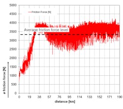
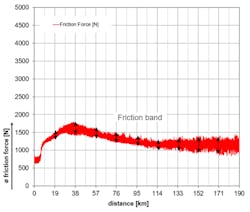
The seals’ friction force levels and bands. The friction level and band should be minimized to improve long-term performance. High friction levels increase temperatures, which shortens seal life. The height of the friction band indicates how well the primary rod seal is lubricated.
Intermediate pressure between buffer and primary rod seal. Buffer seals must prevent intermediate pressure build-up to protect the primary rod seal. In heavy-duty applications, pressure spikes can exceed 600 bar and should be handled by the buffer seal. The primary rod seal is often a U-cup made of polyurethane; it handles pressures up to 400 bar. Therefore, the overall distance where intermediate pressure is higher than 60% of the system pressure and the time to build up intermediate pressure were analyzed.
Visual analysis of buffer and primary rod seal before and after testing. Researchers looked at wear and extrusion on the seal, as well as discoloration. The before-and-after comparison provides direct evidence of seal performance. For example, if the buffer seal is not working properly and there’s evidence of leaks, the primary rod seal will show high extrusion due to intermediate pressure. And if there’s discoloration at the sealing lip of the primary rod seal, the buffer seal was too tight and did not allow enough lubrication to get to the primary rod seal.
Leaks. Generally, oil that escapes from the hydraulic cylinder into the environment must be kept on a minimum level. Recall that the chances for leaks increases as the ratio of outstroke to instroke piston-rod velocities increases. In addition, the primary rod seal needs good back-pumping ability. This is important for the buffer and primary rod seals.
The lubrication level determines the friction level. But the lubrication level also determines the number of leaks. The lubrication level is influenced by instroke and outstroke piston rod velocity, as well as seal design and hydraulic oil used.
The tests were done in four phases:
Running-in phase, to set up constant starting conditions for each seal to guarantee correct comparisons.
Pre-performance phase, to evaluate characteristics such as absorbing pressure spikes and time to build up intermediate pressure.
Long-term phase, to evaluate characteristics such as wear and extrusion resistance.
Post-performance phase, to evaluate characteristics as the seals age.
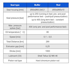
The testing parameters include several different pressure and piston rod velocity cycles, with pressures and piston rod velocities set so that pressure was low when speed was high and vice-versa. This mimics an operating excavator; the high loads are mostly at low operating speeds, and the higher speeds go with low loading.
Test Results
1. Lip seal without back-up ring. The graph above shows the system and intermediate pressure curve of seal #11 at the pre-performance test. It is clearly visible that the intermediate pressure increases immediately. Over 96% of the entire testing distance, intermediate pressure equaled the system pressure which means no buffering capability is available.
After the running-in phase, the first day of testing started with constant in- and outstroke piston rod velocity. After about a kilometer of motion, intermediate pressure equals system pressure. After a full system shutdown overnight, the second day started with twice the outstroke piston rod velocity. This caused a quick build-up of intermediate pressure to system pressure, which system pressure and pressure spikes must be handled by the primary rod seal. In this case, the pre-performance test was extended but it was not possible to decrease the intermediate pressure.
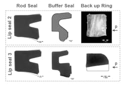
The above images show damage to the seal’s profiles. The buffer seal didn’t show any major damage. But the primary rod seal already shows some wear and extrusion after a testing distance of 90 km. The seal did no work as expected.
2 and 3. Lip seals with back-up ring. The above images show the friction levels before and after the performance tests, as well as changes to the seal profile after the entire endurance test of both lip seals with back-up rings. The difference between a “friction optimized” buffer seal (2) and a “high sealability” buffer seal (3) can clearly be seen in the different friction levels. The increased friction of seal lip #3 increased the entire system’s temperature and led to higher wear on the back-up ring. Furthermore, the primary rod seal’s lip is discolored due to inadequate lubrication.
There is only a slight extrusion tail at the back-up ring of lip seal 2 and nearly no visual damage of the sealing element. The rod seal lip preload was less affected when combined with lip seal 2 due to lower operating temperatures as a consequence of better lubrication.
The friction level for 3 decreased between pre- and post-test measurements. This likely stems from the smaller back-up ring cross section due to wear. Seal 2, on the other hand, had a slight increase in friction after the tests. It can be explained by more contact area on the back-up ring caused by light deformations.
The charts above show the system and intermediate pressure for seal 2. It has a relatively low intermediate pressure (below 50 bar at 250 bar system pressure), thanks to its design. Deformation of the back-up ring led to better sealability as it ages, lowering the likelihood of building up intermediate pressure and lower levels of lubrication.
Lip seal 3 shows no intermediate pressure during all different system pressure levels. This indicates that 3 has a high sealability at all pressure levels. Both design concepts (lip seal 2 and 3) showed low to no leaks in combination with the primary rod seal.
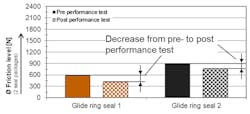
4 and 5. O-ring energized glide ring seals. The above figure graphs chart friction level of glide ring seal 4 and 5 at pre- and post-performance test as well as profile cut analysis after the whole verification test.
Seal 4 demonstrates little friction. The PTFE element shows extrusion in both directions because it sealed in both directions and did not vent intermediate pressure as desired. As a consequence, the primary rod seal showed extrusion, which confirms that glide ring seal 4 was ineffective in reducing pressure spikes.
Glide ring seal 5 has slightly more friction than 4, but still an acceptable good level. The decrease in friction after the test is lower compared to glide ring seal 4 because of increased wear and extrusion resistance of the hard grade polyurethane glide ring.
The graphs above show intermediate pressure at 50-bar of backstroke system pressure during the long-term test for both 4 and 5 glide ring seals. Seal 4 immediately built-up intermediate pressure to a multiple system pressure level, the result of no venting capability. Seal 5 shows no to low intermediate pressure built-up at several pressure stages between 50 and 400 bar.
Here’s a comparison of leaks with Seals 4 and 5. The good performance of Seal 5 improves the performance of the entire rod seal package; it had far fewer problems with leaks than Seal 4.
The results clearly demonstrate that it is very important to consider the operating parameters when selecting the buffer seal. Lip-type buffers with thermoplastic back-up rings can handle high pressures, while O-ring energized glide ring seals have limitations in extrusion resistance, especially in Bronze filled PTFE (which showed unacceptable extrusion). Consequently, these seals should only be used in medium-duty applications. Lip type buffers without back-up rings and round sealing edge didn’t work as expected and show no improvement compared to systems without an additional buffer seal.
Future evaluations of rod seal packages, including buffer, primary rod seal and wiper, are already underway. The goal is to find rod seal packages for applications from light- to heavy-duty that guarantee longest service life of the entire sealing system.
Thomas Schwarz is manager of testing, materials technologies & research; Wolfgang Swete is manager of product technology and development; Silvio Schreymayer, is manager of testing; Martin Wallner is the manager or product development; Emmanuel Pichlmaier is a product development engineer; and Michael Liebminger is a testing engineer for SKF Seals.
About the Author
Thomas Schwarz
Manager of Testing, Materials Technologies & Research, SKF Seals
Wolfgang Swete
Manager of Product Technology and Development, SKF Seals
Silvio Schreymayer
Manager of Testing, SKF Seals
Emmanuel Pichlmaier
Product Development Engineer, SKF Seals
Martin Wallner
Manager of Product Development, SKF Seals
Michael Liebminger
Testing Engineer, SKF Seals

Leaders relevant to this article:
