How to Recognize and Avoid the Common Causes of O-ring Failure
Download this article as a .PDF file.
O-rings are the most commonly used seals in fluid-power systems. However, elastomeric O-rings are unlike most of the materials that engineers and designers encounter. The reason: O-rings must deform to function properly.
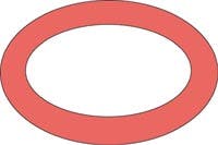
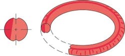
As the name implies, O-rings are shaped like a doughnut. (Torus is the geometric term.) They are installed in cavities known as glands and then compressed. The resulting zero clearance within the gland provides the seal that blocks the flow of liquids and gases. This simple arrangement serves many fluid-power systems very well, but success still requires careful design, selection, and installation procedures.
O-rings typically fail in their applications because of the combined adverse effects of several environmental factors. Experience has shown the most common causes of O-ring failure are:
• improper gland design — allowing for too much or too little compression, not enough room for displacement under compression, or tolerance stack-up
• incorrect O-ring size
• incompatibility between the O-ring elastomer and environmental elements it must contact
• improper O-ring installation, and
• inadequate O-ring lubrication.
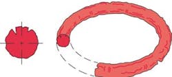
The combination of stresses that act on O-rings can be complex and difficult to evaluate. Therefore, both the O-ring compound and size should be tested in the real environment of its service. The following examples picture and classify the common types of O-ring failure that can occur.
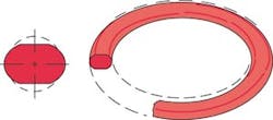
Failure without visible evidence on seal
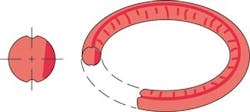
Problem sources: Insufficient compression . . . Tolerance stack-up . . . Eccentric-shaped components . . . Parting lines and/or flash left on the O-ring from the molding process. . . Improper volume relationship between the seal and its gland.
Suggested solutions: Maintain recommended compression range for the application . . . Identify the amount of stretch as it reduces the O-ring cross section with increased stretch . . . Determine the component tolerance stack-up as it directly affects the seal cross section . . . Consider maximum component shift in design to ensure that compression is still contained within recommended compression range . . . Avoid parting lines in O-ring grooves as they tend to be areas of flash and mismatch . . . Ensure that the O-ring gland volume surpasses the O-ring volume to allow for seal expansion without seal detriment.
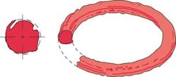
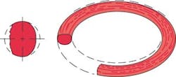
Compression set
Problem sources: The selected elastomer has poor compression-set properties . . . Low heat resistance of material . . . Excessive swelling of O-ring material in system fluid . . . Too much squeeze to achieve seal . . . Incomplete curing (vulcanization) of the O-ring material during production.
Suggested solutions: Use a low set elastomer . . . Specify an O-ring material that resists both operating and friction-generated heat . . . Re-check O-ring material compatibility with system chemicals . . . Reduce O-ring squeeze if possible . . . Inspect incoming O-rings for correct physical properties.
Extrusion and nibbling
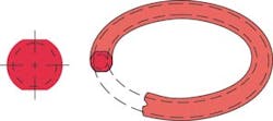
Problem sources: Excessive gland clearances . . . Excessive system pressure . . . O-ring material too soft . . . Degradation of O-ring by system fluid . . . Irregular clearance gaps caused by eccentricity . . . Improper machining of O-ring gland (leaving sharp edges) . . . O-ring size too large for gland.
Suggested solutions: Decrease gland clearances by machining . . . Use back-up rings to prevent extrusion . . . Use harder O-ring material . . . Re-check elastomer compatibility with system chemicals . . . Increase rigidity and improve concentricity of metal components . . . Break sharp edges of gland to a minimum radius of 0.005 in. . . . Install proper size O-ring . . . Consider substituting a reinforced composite seal, such as rubber bonded to metal.
Abrasion
Problem sources: Metal surfaces of gland are too rough and act as an abrasive . . . Metal surfaces are too smooth causing inadequate lubrication . . . Poor lubrication . . . Excessive temperatures . . . System fluid contaminated with abrasive particles.
Suggested solutions: Use recommended metal finishes . . . Provide adequate lubrication (consider internally lubricated O-rings) . . .Check material compatibility with system temperature . . . Eliminate abrasive contamination with filters and/or wiper seals . . . Consider changing to a more abrasion-resistant O-ring material, such as carboxilated nitrile or urethane.
Heat hardening and oxidation
Problem sources: Excessive temperature causing elastomer hardening, evaporation of plasticizers, and cracking from oxidation.
Suggested solutions: Specify high temperature O-ring materials with antioxidants . . . Lower operating temperature of hydraulic system.
Damage during installation
Problem sources: Sharp edges on mating components of the O-ring gland . . . Sharp threads over which the O-ring must pass during assembly . . . Insufficient lead-in chamfer . . . Oversized O-ring ID on piston . . . Undersized O-ring ID on rod . . . O-ring was twisted or pinched during installation . . . O-ring was not lubricated during installation . . . O-ring elastomer has low tear resistance (typical of silicone).
Suggested solutions: Break all sharp edges . . . Cover threads with tubes or tape during O-ring installation . . . Provide a 15° to 20° lead-in chamfer . . . Install correctly sized O-rings . . . Use lubrication during assembly.
Excessive swell
Problem sources: Like a sponge, the seal absorbs the surrounding fluids and swells to the point of malfunction because of incompatibility between seal compound and system environment (i.e. chemical incompatibility, high humidity, etc.).
Suggested solutions: Select an O-ring material that is chemically compatible with the fluid it will contact.
Spiral failure
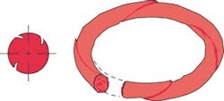
Problem sources: Caused when some segments of the O-ring slide while other segments simultaneously roll. At a single point on its periphery, the O-ring gets caught on an eccentric component or against the cylinder wall, causing twisting and development of 45° angle surface cuts.
Contributing conditions include: Eccentric components . . . Wide clearance combined with side loads . . . Uneven surface finishes . . . Inadequate lubrication . . . O-ring material is too soft . . . Stroke speeds are too slow.
Suggested solutions: Check the cylinder bore — it may be out of round . . . Decrease the clearance gap . . . Machine metal surfaces to a 10- to 20-µin. finish . . . Improve lubrication (consider substituting internally lubricated O-rings) . . . Increase O-ring material hardness and/or cross-sectional area . . . Add anti-extrusion back-up rings.
Weather or ozone cracking
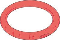
Problem sources: Ozone attacks the polymer chains, causing O-ring material to crack.
Suggested solutions: Substitute O-ring elastomers that are resistant to ozone attack.
Explosive decompression
Problem sources: Absorption of gas by O-ring while operating in high pressure conditions. Subsequent rapid decrease in system pressure traps gas within the O-ring's micropores, causing surface blisters and ruptures as the gas escapes.
Suggested solutions: Increase the time for decompression . . . Change to a material that has a hardness in the 80- to 95-durometer range . . . Reduce the O-ring's cross-sectional size.
Mark Messinger is an engineer at Apple rubber Products, Lancaster, N. Y. For more informaation, call (800) 828-7745 or visit www.applerubber.com.
Tool identifies O-ring material
Almost by definition, all O-ring seals look pretty much alike. With some basic measuring devices, a mixed bag of O-rings can be sorted by size, but how can you identify their material for chemical compatibility - and do it without destroying the O-ring? One way: use the ORID 70-C O-ring identifier, built by Bachus Instrument Co., Nashville.
The stainless-steel ORID 70-C will accurately read 100, 200, 300, and 400 Series (0.103 to 0.275 in.) cross-section O-rings with durometer hardness of 60, 70, or 80. Note that the surface supporting the O-ring should be hard and rigid. The ORID 70-C tool should not be used with damaged or failed O-rings, or O-rings older than their indicated shelf life, and it cannot identify material correctly that is not in an O-ring configuration.
For more information, call Bachus Instrument at (615) 361-7295, email [email protected] or visit www.bachusinc.com.
