Troubleshooting Challenge: Speed Control Causing Unwanted Jolt and Pressure Spike
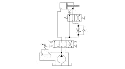
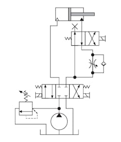
A casting plant used a simple two-speed circuit to extend a hydraulic cylinder at high speed, then shift to a slower speed for forming. The maintenance supervisor used the accompanying schematic to plumb the circuit.
A problem occurred when the cylinder shifted to low speed—the nesting of the steel stamping bounced out of alignment with a hole bored in the fixture. Shifting the two-position directional valve, B, to slow pressing speed produced a jolt and a pressure spike, which caused unwanted movement of the stamping.
Maintenance personnel purchased and installed a soft-shift directional valve with a 500-ms shifting speed, but it made the problem worse. They re-installed the original directional valve, A, and installed a pressure gauge in the piping between the cylinder’s rod end and the two-position valve. The cylinder had a 5-in. bore and a 3½-in. rod diameter. They were surprised that the pressures jumped from 350 psi during fast advance to 4,000 psi when the slow-speed meter-out flow control was selected. The pump compensator was set at 2,000 psi.
Any idea what caused the problem?
Last month’s problem: Unexpected pressure loss while testing a new hydraulic power unit
When I was manager of a large hydraulic-power-unit (HPU) fabrication shop, we had a strange problem while testing a large HPU. It consisted of a large vane pump, a pilot-operated relief, and a 5-bank D08 manifold with 3-position blocked center directional valves with pressure reducing modules. All of the A and B ports contained pressure gauges. The HPU had a separate off-line filtration and cooling circuit, which we commonly refer to as a kidney loop. The pump was driven by a 100-hp, 1800-rpm electric motor — a large HPU, but a fairly simple system.
The system pressure was set to 2250 psig with an output flow of 75 gpm. The pump would run for 30 to 60 seconds at a time under pressure, but then all pressure would quickly drop to near 0 psig for two to three seconds. Pressure would then quickly jump back up to 2250 psig. This happened 15 to 20 times before the test mechanic called me for help.
The unit piping had about ½-in. NPT and ½-in. O-ring connections. No Teflon tape was used, just white, paste-type pipe dope for sealing the NPT connections. We felt the only valve that could cause the malfunction was the pilot-operated relief, so we dis-assembled and inspected it. We did this at least four or five times and could not see any contamination or sticking problem.
We were pressed to move onto other units on the test stand, so we drained the oil from the reservoir and removed its access panels, with the eventual plan of retesting it later. However, we noticed that the reservoir bottom was covered with typical construction debris and a rather large amount of small beads of excess pipe dope. Any idea what was causing the problem?
Solution:
Many people do not allow the use of PTFE (Teflon) tape for sealing NPT fittings. However, excessive pipe dope during construction can lead to failure of pilot-operated relief valves when the pipe dope oozes through the control orifice. This causes the valve to open until the pipe dope exits, then the valve resets itself.
The unit was dis-assembled, cleaned of all excess pipe dope, re-assembled, tested with good results, and shipped to the customer.


