As the economy started improving after the recent downturn, several hydraulic distributors were adding new people that sometimes got in over their head designing circuits for their customers. We received a call from a new salesman asking for our help in solving problems he was having with a system he designed and installed.
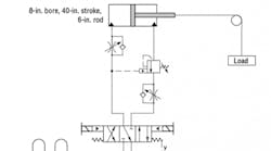
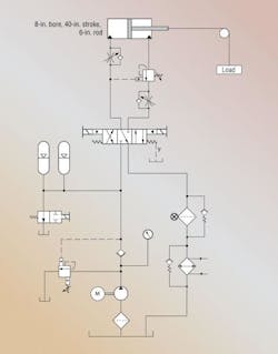
He sent the circuit shown at right to us for review and comment. The problems he was experiencing were as follows:
When debugging the system, the customer blew a 25 gpm spin-on filter element off its filter head. He bypassed it for the time being.
The safety ISO-3 “solenoid dump valve” for the accumulators chattered when energized. The customer also indicated the electric motor’s current draw fluctuated.
Another concern was with how high the counterbalance valve adjustment had to set and how the “extend flow control” adjustment was very sensitive.
What would you have advised him to do?
Robert J. Sheaf, Jr. is the founder of Certified Fluid Consultants (CFC) and President of CFC-Solar Inc. CFC-Solar provides technical training, consulting, and field services to any industry using fluid power technology. Visit www.cfc-solar.com for more information.
Find the solutionThink you know the answer? Submit solutions to [email protected]. The correct answer will be published in the next edition of “Troubleshooting Challenge.” All correct solutions will be entered for a chance at a $50 gift card — we will randomly select a winner from all correct answers. The winner’s name will be printed in the next edition of “Troubleshooting Challenge.” Congratulations to Sam Burkett, Sr. Development Engineer, Hiller Nuclear Range at Rotork, who correctly answered the May Troubleshooting Challenge and was selected for the gift card. |
Solution to May’s rock crusher problem
The overheating problem with the rock crusher machine was interesting in that it overheated when idling or coasting but if loaded for hours, the cooler handled the heat exchange.
However, when idling or coasting, the large pressure compensated pump was fully compensated at 3000 psi, and the hot case drain oil was not cooled. The case drain was plumbed directly to the tank while the cooler didn’t see any system oil flow to cool.
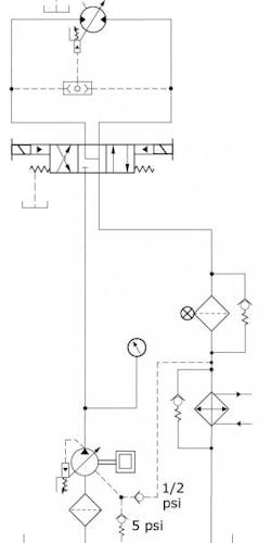
We have found that providing the pump case drain with a set of check valves — one with a 5 psi setting plumbed to the tank and the other a ½ to 1 psi plumbed to the main cooler — would have reduced idle heat buildup in the system. When the system is working, fluid flows from the actuators, and while idling, the only heat source from the pump case drain is cooled. This solved their problem.
If the operating system does not require a heat exchanger, but idles for long periods of time, a small air cooled heat exchanger can be installed on the case drain of pump.


