Matching the performance characteristics of a servo or proportional valve to the performance needs of an application requires at least two major system design steps:
1. The valve and cylinder must be sized so that the cylinder transmits enough power to the load to simultaneously meet the worst case force and speed design target.
2. There is sufficient bandwidth (frequency response) in the valve and load-compressibility resonance to accurately regulate the output (let us assume it to be cylinder position) at the target value.
The sizing problem is greatly facilitated by adopting the concept of valve flow coefficient rather than the valve flow rating process that is popular with valve manufacturers. We can develop a set of design formulas to derive the valve coefficient, which is not practical with the flow rating method. That’s because servo and proportional valves are flow rated at different pressures. Furthermore, ISO 10770-1 requires that the “valve total pressure drop be set to 1 MPa or 7 MPa, as appropriate.”
A test procedure that specifies only total valve pressure drop does not accommodate valves that are deliberately designed with asymmetrical valve coefficients. Such valves are useful in special applications — for example, when trying to reduce the likelihood of cavitation from an over-running load. Another example is an application that cannot withstand the “turnaround bump” that accompanies cylinder motion when symmetrical valves control asymmetrical (single rod) cylinders.
The asymmetrical valve can be the perfect solution. In the asymmetrical valve, the individual internal metering lands do not open to equal flow areas even though they are all connected to the same spool. Such asymmetry is achieved by using differing numbers of slots or notches on the valve body (sleeve) or on the spool.
The beauty of the valve coefficient approach is that both servo and proportional valves can be accommodated with one set of formulas —equally important, so can symmetrical and non-symmetrical valves and symmetric or non-symmetric cylinders.
Pressure and flow relationships
Most fluid mechanics professors express the characteristics of an orifice in terms of its geometry, contraction coefficient (based on geometric dimensions), and the velocity coefficient. However, in Hydraulic Control Systems, H. E. Merritt convincingly explains his conclusion that most hydraulic valves behave as knife-edged orifices. Furthermore, the relationship between pressure and flow can be approximated by the simple formula:
Q = 100 × A
100 is a constant, lb-in.-sec,
A
P
Q is the resulting flow, in.3/sec.
To properly size a servo or proportional control valve, I propose making a simple substitution in the above equation to introduce the valve coefficient, K
K
The relationship is only approximate, but countless valve manufacturers accept the idea that the flow through a typical hydraulic control valve follows the square root of the differential pressure drop. So I propose a definition to make valve sizing and selection more predictable. I propose defining KV empirically and applying it to valves that can be tested now, rather than for designing a new valve:
K
where K
Qr is the rated flow of the orifice as verified by actual test while the valve is operated at its flow rating pressure, in.3/sec, and
PQ
The flow rating differential pressure distinguishes between the rated pressure of the valve and the pressure drop used for determining or verifying the rated flow of the valve. In the case of servovalves, if you are determining the flow coefficient of the “total valve,” then the flow rating pressure is 1000 psid (7 MPa).
If you are looking at only one of the valve’s two metering lands, with one direction of spool shift, then the flow rating differential pressure is one-half the total, or 500 psid (3.5 Mpa). For proportional valves, the flow rating pressure is 145 psid (1 MPa) for the total valve, but only half that, or 72.5 psid (0.5 MPa), for just one of the two internal metering lands.
This approach removes some of the confusion surrounding high pressure drop valves. It also removes confusion when the valve’s lands are not all of equal flow area. Furthermore, the design formulas that come up later apply to all types of valves, making design and sizing straightforward. If valve manufacturers would publish their empirically derived KVs for their products, then applying them would be much easier.
Manufacturers publish rated flow for valves as a convenience to their users. Unfortunately, it implies that
• it is the maximum flow,
• the pressure drop remains constant,
• it is the only flow allowed, or
• some other misconception. Rated flow is not a property of the valve. It is something the valve has if, and only if, it is operated at its flow rating pressure.
K
How many KV s are there?
I’ve been discussing K
Therefore, when tested in accordance with ISO 10770-1, two lands are connected in series (both have the same flow), and their individual pressure drops add up to the supply pressure — plumbing and other losses notwithstanding. With the valve shifted fully open in one of its two directions, it has some published rated flow, provided the pressure drop is set to the flow rating pressure. The value calculated for KV depends on the value used for the flow rating pressure.
Three scenarios
Three outcomes are possible for the pressure value used in the KV formula:
1. If it is the total, (supply pressure as dictated by ISO), then the resulting coefficient is called KV,Total. It is the combined effect of two individual metering lands in series.
2. If it is the measured differential pressure from the P port to the A port, then the resulting value is called the powered land coefficient, or KVPL. It is the effect of only metering land — the one connecting the P port to the A port.
3. If it is the measured differential pressure from the B port to the T port, then the resulting value is called the return land coefficient, or KVRL. It is the effect of only that land internally connecting the B port to the T port.
Conditions two and three are then repeated with the valve shifted in the opposite direction, and the result is two more values for KV. Note that there are powered and return lands for both directions of spool shift, so there needs to be a designation that distinguishes them:
• KV PL, PA is the powered land coefficient when the spool is shifted to flow P to A,
•
KV RL, PA is the return land coefficient for flow from P to A,
• KV PL, PB is the powered land coefficient for flow from P to B, and
• KV RL, PB is the return land coefficient when shifted to flow P to B.
In the symmetrical valve, all four individual lands have the same value; only the total coefficient is different. But the most important thing is that all the coefficients can be determined from published data, and they can be used to determine flows and pressures at any and all operating conditions.
The VCCM equation
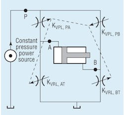
We can develop a method to simultaneously select the optimum components for a given servo-proportional application using the valve coefficient concept and Bernoulli’s principle. Figure 1 depicts the starting point for the analysis.
There are four different valve lands, and they control the power delivered to the two ends of a cylinder. Shifting the spool to extend the cylinder (P to A and B to T) opens KVPL, PA and KVRL, BT, while KV PL, PB and KV RL, AT are in overlap — that is, they are essentially shut off.
The mathematical procedure involves solving for the cylinder pressures on both sides of the piston in relation to the supply pressure, valve coefficients, valve ratio, and cylinder ratio. The math also takes into account the load variables, speed of propulsion, and load force. The result is the VCCM equation, which is solved to size the components for optimal operation. The pressure drop across the valve is implicit in the equation:
fL = PS APE –v2(APE3÷ KVPL2) (1+ρv2÷ ρc2)
where fL is the load force that must be overcome,
PS is supply pressure,
APE is the cylinder size,
v is the speed of cylinder propulsion,
KVPL is the degree to which the valve is open,
ρv is the symmetry of the valve, and
ρc is the cylinder area ratio (cap side of piston area/rod side area).
Solutions to the equation can be used for analyzing the system to ensure that the operating envelope is adequate for the application. The operating envelope is constructed from the VCCM equation with the valve fully open and the valve coefficient at its maximum value. The operating envelope describes the force and velocity available for a given system.
The VCCM equation is the basis for all sizing procedures. If the valve, cylinder, and supply pressures are not properly sized, results can be less than the required degree of control or poor system performance. The worst case is that the application will not meet its design goals.
Pressure metering characteristics define the stopping conditions, including pressures at a given load and the stopping position within the VCCM equation. More specifically, the valve ratio, ρv, and the cylinder ratio, ρc, from the VCCM equation are defined as:
ρv = KVPL÷ KVRL and ρc = APE÷ ARE.
Note that two different values are used for the valve ratio: one for extending the cylinder, and one for retracting it. Similarly, two different values are used for the cylinder ratio, depending on whether it is extending or retracting. The value for extending is greater than one, and the value for retracting is less than one.
Closing the loop
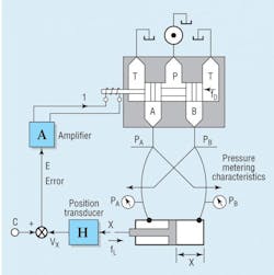
The system in Figure 2 illustrates the positional servomechanism, which is the ultimate subject of this discussion. The cylinder in Figure 2 transmits some load force, fL, while its piston is connected to a position sensing transducer with a transfer characteristic of H, the feedback signal. The value of H is a voltage that goes into an error calculator, where it is subtracted from the command voltage, C. The error signal, E is fed into the servo/proportional amplifier to shift the valve.
As long as the error signal is not zero, the valve will shift, causing the cylinder to move the load to a point where command and feedback signals are equal. In this state, the error is zero, the valve current goes to zero, the spool centers, and the load and cylinder stop. In principle, that is how it works. In reality, it is a bit more complicated.


