Hydraulic accumulators store hydraulic fluid under pressure to supplement pump flow and reduce pump capacity requirements, maintain pressure and minimize pressure fluctuations in closed systems absorb shocks, and provide auxiliary hydraulic power in an emergency. Here’s how.
The Basics
A hydraulic accumulator is a pressure vessel containing a membrane or piston that confines and compresses an inert gas (typically nitrogen). Hydraulic fluid is held on other side of the membrane. An accumulator in a hydraulic device stores hydraulic energy much like a car battery stores electrical energy.
Its initial gas pressure is called the “precharge pressure.” When the system pressure exceeds the precharge pressure, the nitrogen gas is squeezed, compresses and decreases in volume, letting hydraulic fluid into the accumulator. The accumulator’s fluid volume increases until the system reaches its maximum pressure (P2). When system pressure decreases, the nitrogen gas expands and forces the fluid out of the accumulator, providing power to the hydraulic system, until the system and accumulator pressures equalize (P1).
Properly used accumulators increase hydraulic system performance and efficiency, lower operating and maintenance costs, provide fail-safe protection and extend system life by minimizing failure of pumps, pipes and other components.
What Accumulators Do
Here are the top reasons for using accumulators:
To supplement pump flow. The most common use for accumulators is to supplement pump flow. Some hydraulic circuits need high-volume flow, but only for a short periods, and then use little or no fluid for an extended period. When half or more of the machine cycle does not use pump flow, designers usually install an accumulator circuit.
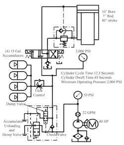
Accumulators need a pressure drop to operate. In some cases, the final design calls for a higher pressure than initially planned. For example, in the circuit shown above, it takes at least 2,000 psi to perform the work, but the accumulators must be filled to a higher pressure so they can supply extra fluid without dropping below the system’s minimum pressure. So, this circuit uses 3,000-psi maximum pressure to store enough fluid to cycle the cylinder in the allotted time and still have enough force to do the work.
The circuit uses several accumulators to supplement pump flow because the dwell time is 45 sec. out of the 57.5-sec. cycle. Its 22-gpm fixed-volume pump operates on pressure during most of the cycle to fill the cylinder and accumulators. Without the accumulators, this circuit would require a 100-gpm pump driven by a 125-hp motor. Although the initial cost for a smaller pump and motor plus the accumulators may be close to that of the larger pump and motor, energy savings over the machine’s life makes this accumulator circuit more economical.
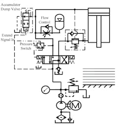
To maintain system pressure. Accumulators often maintain pressures in hydraulic circuits while the pump is unloaded. This is especially useful when using fixed-volume pumps on long holding cycles. For example, adding an accumulator, flow control and pressure switch to the fixed-volume pump circuit shown above lets the pump unload when pressure is at or above the pressure switch’s minimum setting. If leaks at the valve or cylinder seals lets pressure drop about 5%, the pressure switch shifts the directional control and the accumulator pressurizes the cylinder cap end and builds pressure back to maximum. The only time the pump is loaded is when fluid is required. This circuit operates a laminating press that clamps material and holds it under force for one to five minutes. If flow across the relief valve were at high pressure for all that time, it would generate too much heat, wasting energy.
To absorb shock. Fast-moving hydraulic circuits often create pressure spikes that cause shocks when flow abruptly stops. Accumulators in these shock-prone circuits lower these damaging pressure and flow spikes to an acceptable rate or eliminate them completely. Accumulators also handle other pressure-spike concerns in special instances with modified valves.
Accumulators also eliminate pressure spikes caused by sudden flow blockages. The nitrogen charge in this case is usually kept 5% below the working pressure to ensure the accumulator is out of the circuit except during pressure spikes. Bladder-type accumulators work best at this because of their fast responses to pressure changes, so long as the maximum spike pressure doesn’t exceed four times the precharge pressure.
To dampen. Pulsations are another form of shock in hydraulic lines that can damage piping and other system components. Reciprocating pumps, by design, create pressure pulsations, vibrations and noise in the system. Accumulators and related silencers and dampeners can greatly reduce the shockwave energy.
Provide emergency power. Some hydraulically operated machines must be stopped in the open position so as not to damage products or equipment. When power failures shut off the hydraulic pump and the machine is in some position, there must be a way to move it to the open position. An engine-driven standby pump is one choice, but another option is to use accumulators charged before the first cycle and held until the machine shuts down. Their stored energy is then ready to cycle the machine to the open position in case of a power failure.
Other applications. Accumulators are sometimes used in systems in which thermal expansion could cause excessive pressure. Blocked ports on cylinders in areas with high ambient heat create high pressure if there is no place for expanding fluid to go. Accumulators also serve barriers between two different fluids, such as in a system where a pump uses hydraulic fluid to keep pressure on a circuit that uses water or another incompatible medium. One supplier also offers low-pressure accumulators as breathing devices for sealed reservoirs. This keeps airborne contaminants out of the hydraulic oil as the fluid level rises and falls.
Accumulator Types
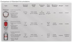
There are three commonly used types of accumulators in industrial applications: bladder, diaphragm and piston. There are several other variations.
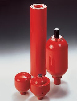
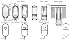
Gas-charged bladder. Many accumulators use a rubber bladder to separate the gas and liquid. A poppet valve in the discharge port keeps the bladder from coming through the port when the pump is off. The original design, still offered by many manufacturers, is the bottom-repair style (shown above on the left). The top-repair style (the right) makes bladder replacement easier in some cases.
Gas-charged piston. A gas-charged piston accumulator has a free-floating piston with seals that separate the liquid and gas. It operates and performs similarly to the bladder type. It some advantages in certain applications, but can cost twice as much as an equal-sized bladder type.
Spring-loaded piston. Spring-loaded piston accumulators are identical to gas-charged units, except a spring forces the piston against the liquid. Its main advantage is that there is no gas to leak. A main disadvantage is that this design is not suitable for high pressure and large volume.
Diaphragm accumulators. There are also diaphragm accumulators with either resilient or metal diaphragms. They are used mainly where the stored volume is small, making them practical for many mobile applications but limiting their use in industrial applications.
What Type to Use?
Some applications can use almost any type accumulator with satisfactory results. However, there are cases where one style is more responsive or offers a longer service life. For example, the amount of pre-charge pressure is a factor to consider when selecting bladder or piston accumulators.
Piston accumulators respond slowly to pressure buildup, so they do not work as well as shock absorbers. This means that although they reduce pressure spikes, they will not stop them. In these situations, the best choice is a bladder or diaphragm accumulator.
Bladder or diaphragm accumulators are the best types when it comes to dampening high-pressure spikes at the outlet of a piston pump. A piston accumulator cannot respond quickly enough, and the short stroke of the piston and seals can cause excessive wear to the bore and seals.
Hydac, a major manufacturer of accumulators and other hydraulic components, lists the following factors as primary selection considerations for the three main types of accumulators (bladder, diaphragm and piston):
- Application (energy storage, shock absorbing or damping pulsations)
- System pressure, maximum and minimum
- Required system fluid volume
- Flow rate
- Pressure Ratio (max. pressure/precharge pressure)
- Installation envelope and mounting position
Pressure Considerations
An accumulator charges when system pressure increases, causing fluid to flow into the accumulator and compressing the nitrogen gas. It is discharged when system pressure decreases, letting nitrogen in the accumulator expand and send the fluid out of the accumulator.
Typically, gas-charged accumulators are pre-charged to approximately 90% of the system’s minimum working pressure. This ensures the bladder or piston does not discharge all the fluid during every cycle. If all fluid is evacuated quickly, bladders can get caught in the poppet valve, and pistons can deform when metal hits metal. In certain applications, this 90% figure may be low because minimum system pressure is low.
In such cases, use piston-type accumulators because the piston can move up the bore almost any distance without damage. A bladder accumulator should not be used when pre-charge pressure is below 25% of the maximum pressure. This avoids compressing the bladder so tightly that it rubs on itself, which can create holes in it.
The design and physical construction of bladder and diaphragm accumulators limits their maximum operating pressure ratios. Exceeding those limits can damage the bladder or diaphragm. A piston accumulator accommodates higher pressure ratios because it does not have an elastomer membrane subject to damage.
Accumulator Safety
- Always arrange some way to drain the accumulator at shut down. Never work on a circuit with an accumulator until you are sure it is depressurized. This is critical because accumulators store energy that can be a safety hazard and damage the machine.
- Make sure accumulator flow is restricted to a reasonable rate during operation and shut down to avoid damaging the machine or piping. Accumulators discharge fluid at any rate the exit flow path will allow. Such high flows do not last long, but the damage it causes can happen in an instant.
- Always isolate the pump from the accumulator with a check valve so fluid cannot back-flow into the pump. Without a check valve, accumulator backflow can drive the pump backward and even overspeed it to destruction in some instances.
- Check the accumulator’s pre-charge pressure when it’s installed and at least once a day for the first week of operation. If there is no noticeable loss of pressure during this time, check again a week later. If all is well, do a routine check every three to six months after that. Whenever the accumulator pre-charge drops below nominal pressure, the volume of available fluid is reduced, which slows the cycle.
Sizing Accumulators
The amount of fluid volume an accumulator can deliver to a system depends on the application. These are the minimum parameters required to determine fluid volume and/or accumulator size:
- Pre-charge pressure (P0)
- Maximum system working pressure (P2)
- Minimum system working pressure (P1)
- Effective gas volume (V0) and usable fluid volume (ΔV)
The size listed for an accumulator refers to its total nominal gas volume, not its fluid capacity. The volume of fluid an accumulator provides for a particular application depends on the system’s differential pressure. Manufacturers offer computer programs that may require only the system requirements to determine the correct accumulator size. Because accumulator sizing depends on many variable factors, it’s always best to consult the supplier for specific information about selection and sizing.
