Engineering Essentials: Fundamentals of Hydraulic Pumps
*Editor's Note: This article was updated in February 2024.
When a hydraulic pump operates, it performs two functions. First, its mechanical action creates a vacuum at the pump inlet which allows atmospheric pressure to force liquid from the reservoir into the inlet line to the pump. Second, its mechanical action delivers this liquid to the pump outlet and forces it into the hydraulic system.
A pump produces liquid movement or flow: it does not generate pressure. It produces the flow necessary for the development of pressure which is a function of resistance to fluid flow in the system. For example, the pressure of the fluid at the pump outlet is zero for a pump not connected to a system (load). Further, for a pump delivering into a system, the pressure will rise only to the level necessary to overcome the resistance of the load.
Classifications of Hydraulic Pumps
All pumps may be classified as either positive-displacement or non-positive-displacement. Most pumps used in hydraulic systems are positive-displacement.
A non-positive-displacement pump produces a continuous flow. However, because it does not provide a positive internal seal against slippage, its output varies considerably as pressure varies. Centrifugal and propeller pumps are examples of non-positive-displacement pumps.
If the output port of a non-positive-displacement pump were blocked off, the pressure would rise, and output would decrease to zero. Although the pumping element would continue moving, flow would stop because of slippage inside the pump.
In a positive-displacement pump, slippage is negligible compared to the pump's volumetric output flow. If the output port were plugged, pressure would increase instantaneously to the point that the pump's pumping element or its case would fail (probably explode, if the drive shaft did not break first), or the pump's prime mover would stall.
Positive-Displacement Principle
A positive-displacement pump is one that displaces (delivers) the same amount of liquid for each rotating cycle of the pumping element. Constant delivery during each cycle is possible because of the close-tolerance fit between the pumping element and the pump case. That is, the amount of liquid that slips past the pumping element in a positive-displacement pump is minimal and negligible compared to the theoretical maximum possible delivery. The delivery per cycle remains almost constant, regardless of changes in pressure against which the pump is working. Note that if fluid slippage is substantial, the pump is not operating properly and should be repaired or replaced.
Read "Principles of Hydraulic Pump Engineering" for the Spanish translated version of this article. / Lea "Principios de ingeniería de bombas hidráulicas" para ver la versión traducida al español de este artículo.
Positive-displacement pumps can be of either fixed or variable displacement. The output of a fixed displacement pump remains constant during each pumping cycle and at a given pump speed. The output of a variable displacement pump can be changed by altering the geometry of the displacement chamber.
Other names to describe these pumps are hydrostatic for positive-displacement and hydrodynamic pumps for non-positive-displacement. Hydrostatic means that the pump converts mechanical energy to hydraulic energy with comparatively small quantity and velocity of liquid. In a hydrodynamic pump, liquid velocity and movement are large; output pressure actually depends on the velocity at which the liquid is made to flow.
Types of Positive-Displacement Pumps
There are several types of hydraulic pumps to which the positive-displacement principle is applied.
Reciprocating Pumps
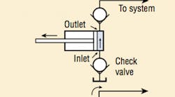
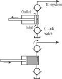
The positive-displacement principle is well illustrated in the reciprocating-type pump, the most elementary positive-displacement pump, Figure 1. As the piston extends, the partial vacuum created in the pump chamber draws liquid from the reservoir through the inlet check valve into the chamber. The partial vacuum helps seat firmly the outlet check valve. The volume of liquid drawn into the chamber is known because of the geometry of the pump case, in this example, a cylinder.
As the piston retracts, the inlet check valve reseats, closing the valve, and the force of the piston unseats the outlet check valve, forcing liquid out of the pump and into the system. The same amount of liquid is forced out of the pump during each reciprocating cycle.
All positive-displacement pumps deliver the same volume of liquid each cycle (regardless of whether they are reciprocating or rotating). It is a physical characteristic of the pump and does not depend on driving speed. However, the faster a pump is driven, the more total volume of liquid it will deliver.
Rotary Pumps
In a rotary-type pump, rotary motion carries the liquid from the pump inlet to the pump outlet. Rotary pumps are usually classified according to the type of element that transmits the liquid, so that we speak of a gear-, lobe-, vane-, or piston-type rotary pump.
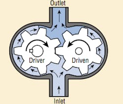
External-gear pumps can be divided into external and internal-gear types. A typical external-gear pump is shown in Figure 2. These pumps come with a straight spur, helical, or herringbone gears. Straight spur gears are easiest to cut and are the most widely used. Helical and herringbone gears run more quietly, but cost more.
A gear pump produces flow by carrying fluid in between the teeth of two meshing gears. One gear is driven by the drive shaft and turns the idler gear. The chambers formed between adjacent gear teeth are enclosed by the pump housing and side plates (also called wear or pressure plates).
A partial vacuum is created at the pump inlet as the gear teeth unmesh. Fluid flows in to fill the space and is carried around the outside of the gears. As the teeth mesh again at the outlet end, the fluid is forced out.
Volumetric efficiencies of gear pumps run as high as 93% under optimum conditions. Running clearances between gear faces, gear tooth crests and the housing create an almost constant loss in any pumped volume at a fixed pressure. This means that volumetric efficiency at low speeds and flows is poor, so that gear pumps should be run close to their maximum rated speeds.
Although the loss through the running clearances, or "slip," increases with pressure, this loss is nearly constant as speed and output change. For one pump the loss increases by about 1.5 gpm from zero to 2,000 psi regardless of speed. Change in slip with pressure change has little effect on performance when operated at higher speeds and outputs. External-gear pumps are comparatively immune to contaminants in the oil, which will increase wear rates and lower efficiency, but sudden seizure and failure are not likely to occur.
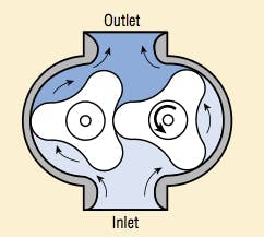
The lobe pump is a rotary, external-gear pump, Figure 3. It differs from the conventional external-gear pump in the way the "gears" are driven. In a gear pump, one gear drive the other; in a lobe pump, both lobes are driven through suitable drives gears outside of the pump casing chamber.
A screw pump is an axial-flow gear pump, similar in operation to a rotary screw compressor. Three types of screw pumps are the single-screw, two-screw, and three-screw. In the single-screw pump, a spiraled rotor rotates eccentrically in an internal stator. The two-screw pump consists of two parallel intermeshing rotors rotating in a housing machined to close tolerances. The three-screw pump consists of a central-drive rotor with two meshing idler rotors; the rotors turn inside of a housing machined to close tolerances.
Flow through a screw pump is axial and in the direction of the power rotor. The inlet hydraulic fluid that surrounds the rotors is trapped as the rotors rotate. This fluid is pushed uniformly with the rotation of the rotors along the axis and is forced out the other end.
The fluid delivered by a screw pump does not rotate, but moves linearly. The rotors work like endless pistons, which continuously move forward. There are no pulsations even at higher speed. The absence of pulsations and the fact that there is no metal-to-metal contact results in very quiet operation.
Larger pumps are used as low-pressure, large-volume prefill pumps on large presses. Other applications include hydraulic systems on submarines and other uses where noise must be controlled.
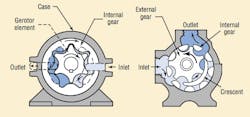
Internal-gear pumps, Figure 4, have an internal gear and an external gear. Because these pumps have one or two less teeth in the inner gear than the outer, relative speeds of the inner and outer gears in these designs are low. For example, if the number of teeth in the inner and outer gears were 10 and 11 respectively, the inner gear would turn 11 revolutions, while the outer would turn 10. This low relative speed means a low wear rate. These pumps are small, compact units.
The crescent seal internal-gear pump consists of an inner and outer gear separated by a crescent-shaped seal. The two gears rotate in the same direction, with the inner gear rotating faster than the outer. The hydraulic oil is drawn into the pump at the point where the gear teeth begin to separate and is carried to the outlet in the space between the crescent and the teeth of both tears. The contact point of the gear teeth forms a seal, as does the small tip clearance at the crescent. Although in the past this pump was generally used for low outputs, with pressures below 1,000 psi, a 2-stage, 4,000-psi model has recently become available.
The gerotor internal-gear pump consists of a pair of gears which are always in sliding contact. The internal gear has one more tooth than the gerotor gear. Both gears rotate in the same direction. Oil is drawn into the chamber where the teeth are separating, and is ejected when the teeth start to mesh again. The seal is provided by the sliding contact.
Generally, the internal-gear pump with toothcrest pressure sealing has higher volumetric efficiency at low speeds than the crescent type. Volumetric and overall efficiencies of these pumps are in the same general range as those of external-gear pumps. However, their sensitivity to dirt is somewhat higher.
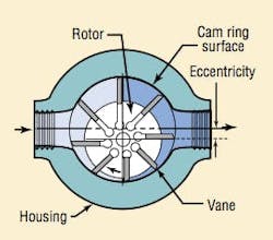
In vane pumps, a number of vanes slide in slots in a rotor which rotates in a housing or ring. The housing may be eccentric with the center of the rotor, or its shape may be oval, Figure 5. In some designs, centrifugal force holds the vanes in contact with the housing, while the vanes are forced in and out of the slots by the eccentricity of the housing. In one vane pump, light springs hold the vanes against the housing; in another pump design, pressurized pins urge the vanes outward.
During rotation, as the space or chamber enclosed by vanes, rotor, and housing increases, a vacuum is created, and atmospheric pressure forces oil into this space, which is the inlet side of the pump. As the space or volume enclosed reduces, the liquid is forced out through the discharge ports.
Balanced and unbalanced vane pumps — The pump illustrated in Figure 5 is unbalanced, because all of the pumping action occurs in the chambers on one side of the rotor and shaft. This design imposes a side load on the rotor and drive shaft. This type vane pump has a circular inner casing. Unbalanced vane pumps can have fixed or variable displacements.
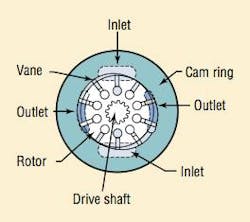
Some vane pumps provide a balanced construction in which an elliptical casing forms two separate pumping areas on opposite sides of the rotor, so that the side loads cancel out, Figure 6. Balanced vane pumps come only in fixed displacement designs.
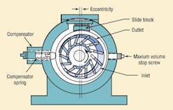
In a variable-volume unbalanced design, Figure 7, the displacement can be changed through an external control such as a handwheel or a pressure compensator. The control moves the cam ring to change the eccentricity between the ring and rotor, thereby changing the size of the pumping chamber and thus varying the displacement per revolution.
When pressure is high enough to overcome the compensator spring force, the cam ring shifts to decrease the eccentricity. Adjustment of the compensator spring determines the pressure at which the ring shifts.
Because centrifugal force is required to hold the vanes against the housing and maintain a tight seal at those points, these pumps are not suited for low-speed service. Operation at speeds below 600 rpm is not recommended. If springs or other means are used to hold vanes out against the ring, efficient operation at speeds of 100-200 rpm is possible.
Vane pumps maintain their high efficiency for a long time, because compensation for wear of the vane ends and the housing is automatic. As these surfaces wear, the vanes move further out in their slots to maintain contact with the housing.
Vane pumps, like other types, come in double units. A double pump consists of two pumping units in the same housing. They may be of the same or different sizes. Although they are mounted and driven like single pumps, hydraulically, they are independent. Another variation is the series unit: two pumps of equal capacity are connected in series, so that the output of one feeds the other. This arrangement gives twice the pressure normally available from this pump. Vane pumps have relatively high efficiencies. Their size is small relative to output. Dirt tolerance is relatively good.
Piston Pumps
The piston pump is a rotary unit which uses the principle of the reciprocating pump to produce fluid flow. Instead of using a single piston, these pumps have many piston-cylinder combinations. Part of the pump mechanism rotates about a drive shaft to generate the reciprocating motions, which draw fluid into each cylinder and then expels it, producing flow. There are two basic types, axial and radial piston; both area available as fixed and variable displacement pumps. The second variety often is capable of variable reversible (overcenter) displacement.
Most axial and radial piston pumps lend themselves to variable as well as fixed displacement designs. Variable displacement pumps tend to be somewhat larger and heavier, because they have added internal controls, such as handwheel, electric motor, hydraulic cylinder, servo, and mechanical stem.
Axial-piston pumps — The pistons in an axial piston pump reciprocate parallel to the centerline of the drive shaft of the piston block. That is, rotary shaft motion is converted into axial reciprocating motion. Most axial piston pumps are multi-piston and use check valves or port plates to direct liquid flow from inlet to discharge.
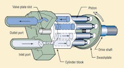
Inline piston pumps — The simplest type of axial piston pump is the swashplate design in which a cylinder block is turned by the drive shaft. Pistons fitted to bores in the cylinder block are connected through piston shoes and a retracting ring, so that the shoes bear against an angled swashplate. As the block turns, Figure 8, the piston shoes follow the swashplate, causing the pistons to reciprocate. The ports are arranged in the valve plate so that the pistons pass the inlet as they are pulled out and the outlet as they are forced back in. In these pumps, displacement is determined by the size and number of pistons as well as their stroke length, which varies with the swashplate angle.
In variable-displacement models of the inline pump, the swashplate swings in a movable yoke. Pivoting the yoke on a pintle changes the swashplate angle to increase or decrease the piston stroke. The yoke can be positioned with a variety of controls, i.e., manual, servo, compensator, handwheel, etc.
Bent-axis pumps — This pump consists of a drive shaft which rotates the pistons, a cylinder block, and a stationary valving surface facing the cylinder block bores which ports the inlet and outlet flow. The drive shaft axis is angular in relation to the cylinder block axis. Rotation of the drive shaft causes rotation of the pistons and the cylinder block.
Because the plane of rotation of the pistons is at an angle to the valving surface plane, the distance between any one of the pistons and the valving surface continually changes during rotation. Each individual piston moves away from the valving surface during one-half of the shaft revolution and toward the valving surface during the other half.
The valving surface is so ported that its inlet passage is open to the cylinder bores in that part of the revolution where the pistons move away. Its outlet passage is open to the cylinder bores in the part of the revolution where the pistons move toward the valving surface. Therefore, during pump rotation the pistons draw liquid into their respective cylinder bores through the inlet chamber and force it out through the outlet chamber. Bent axis pumps come in fixed and variable displacement configurations, but cannot be reversed.
In radial-piston pumps, the pistons are arranged radially in a cylinder block; they move perpendicularly to the shaft centerline. Two basic types are available: one uses cylindrically shaped pistons, the other ball pistons. They may also be classified according to the porting arrangement: check valve or pintle valve. They are available in fixed and variable displacement, and variable reversible (over-center) displacement.
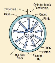
In pintle-ported radial piston pump, Figure 9, the cylinder block rotates on a stationary pintle and inside a circular reacting ring or rotor. As the block rotates, centrifugal force, charging pressure, or some form of mechanical action causes the pistons to follow the inner surface of the ring, which is offset from the centerline of the cylinder block. As the pistons reciprocate in their bores, porting in the pintle permits them to take in fluid as they move outward and discharge it as they move in.
The size and number of pistons and the length of their stroke determine pump displacement. Displacement can be varied by moving the reaction ring to increase or decrease piston travel, varying eccentricity. Several controls are available for this purpose.
Plunger pumps are somewhat similar to rotary piston types, in that pumping is the result of pistons reciprocating in cylinder bores. However, the cylinders are fixed in these pumps; they do not rotate around the drive shaft. Pistons may be reciprocated by a crankshaft, by eccentrics on a shaft, or by a wobble plate. When eccentrics are used, return stroke is by springs. Because valving cannot be supplied by covering and uncovering ports as rotation occurs, inlet and outlet check valves may be used in these pumps.
Because of their construction, these pumps offer two features other pumps do not have: one has a more positive sealing between inlet and outlet, permitting higher pressures without excessive leakage of slip. The other is that in many pumps, lubrication of moving parts other than the piston and cylindrical bore may be independent of the liquid being pumped. Therefore, liquids with poor lubricating properties can be pumped. Volumetric and overall efficiencies are close to those of axial and radial piston pumps.
Measuring Hydraulic Pump Performance
Volume of fluid pumped per revolution is calculated from the geometry of the oil-carrying chambers. A pump never quite delivers the calculated, or theoretical, amount of fluid. How close it comes is called volumetric efficiency. Volumetric efficiency is found by comparing the calculated delivery with actual delivery. Volumetric efficiency varies with speed, pressure, and the construction of the pump.
A pump's mechanical efficiency is also less than perfect, because some of the input energy is wasted in friction. Overall efficiency of a hydraulic pump is the product of its volumetric and mechanical efficiencies.
Pumps are generally rated by their maximum operating pressure capability and their output, in gpm or lpm, at a given drive speed, in rpm.
Matching Pump Power with the Load
Pressure compensation and load sensing are terms often used to describe pump features that improve the efficiency of pump operation. Sometimes these terms are used interchangeably, a misconception that is cleared up once you understand the differences in how the two enhancements operate.
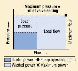
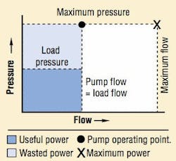
To investigate these differences, consider a simple circuit using a fixed-displacement pump running at constant speed. This circuit is efficient only when the load demands maximum power because the pump puts out full pressure and flow regardless of load demand. A relief valve prevents excessive pressure buildup by routing high-pressure fluid to tank when the system reaches the relief setting. As Figure 10 shows, power is wasted whenever the load requires less than full flow or full pressure. The unused fluid energy produced by the pump becomes heat that must be dissipated. Overall system efficiency may be 25% or lower.
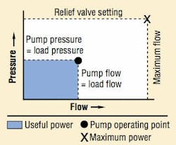
Variable displacement pumps, equipped with displacement controls, Figure 11, can save most of this wasted hydraulic horsepower when moving a single load. Control variations include hand wheel, lever, cylinder, stem servo, and electrohydraulic servo controls. Examples of displacement control applications are the lever-controlled hydrostatic transmissions used to propel windrowers, skid-steer loaders, and road rollers.
While matching the exact flow and pressure needs of a single load, these controls have no inherent pressure or power-limiting capabilities. And so, other provisions must be made to limit maximum system pressure, and the prime mover still must have corner horsepower capability. Moreover, when a pump supplies a circuit with multiple loads, the flow and pressure-matching characteristics are compromised.
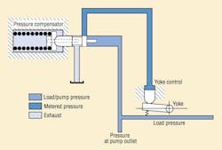
A design approach to the system in which one pump powers multiple loads is to use a pump equipped with a proportional pressure compensator, Figure 12. A yoke spring biases the pump swashplate toward full displacement. When load pressure exceeds the compensator setting, pressure force acts on the compensator spool to overcome the force exerted by the spring.
The spool then shifts toward the compensator-spring chamber, ports pump output fluid to the stroking piston, and decreases pump displacement. The compensator spool returns to neutral when pump pressure matches the compensator spring setting. If a load blocks the actuators, pump flow drops to zero.
Using a variable-displacement, pressure-compensated pump rather than a fixed-displacement pump reduces circuit horsepower requirements dramatically, Figure 13. Output flow of this type of pump varies according to a predetermined discharge pressure as sensed by an orifice in the pump's compensator.
Because the compensator itself operates from pressurized fluid, the discharge pressure must be set higher — say, 200 psi higher — than the maximum load-pressure setting. So if the load-pressure setting of a pressure-compensated pump is 1,100 psi, the pump will increase or decrease its displacement (and output flow) based on a 1,300-psi discharge pressure.
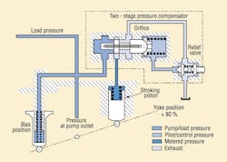
A two-stage pressure-compensator control, Figure 14, uses pilot flow at load pressure across an orifice in the main stage compensator spool to create a pressure drop of 300 psi. This pressure drop generates a force on the spool which is opposed by the main spool spring. Pilot fluid flows to tank through a small relief valve. A spring chamber pressure of 4,700 psi provides a compensator control setting of 5,000 psi.
An increase in pressure over the compensator setting shifts the main stage spool to the right, porting pump output fluid to the stroking piston, which overcomes bias piston force and reduces pump displacement to match load requirements.
The earlier stated misconception stems from an observation that output pressure from a pressure-compensated pump can fall below the compensator setting while an actuator is moving. This does not happen because the pump is sensing the load, it happens because the pump is undersized for the application. Pressure drops because the pump cannot generate enough flow to keep up with the load. When properly sized, a pressure-compensated pump should always force enough fluid through the compensator orifice to operate the compensator.
Two-Stage Control Provides More Dynamic Pump Performance
With respect to its matching function, a two-stage compensator is identical to the proportional compensator control shown in Figure 12. The dynamic performance of the two-stage control is superior, however. This becomes obvious when one analyzes a transient which involves a sudden decrease in load flow demand, starting from full stroke at low pressure.
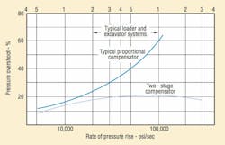
The single-stage control spool ports pressure fluid to the stroke piston only when pump discharge pressure reach the compensator setting. The main-stage spool of the two-stage control starts moving as soon as pump discharge pressure minus spring chamber pressure exceeds the 300-psi spring setting. Because pilot fluid flows through the orifice and because of the flow needed to compress the fluid in the spring chamber, the spring chamber pressure lags pump discharge pressure. This causes the spool to become unbalanced and shift to the right.
Pump destroking starts before pump discharge pressure reaches the compensator setting, Figure 15. Note that in system equipped with an accumulator, a two-stage compensator control provides little advantage. In excavator hydraulic systems, however, superiority of the two-stage compensator is evident: it provides system components much greater protection against pressure transients.
Load Sensing: The Next Step in Control Technology
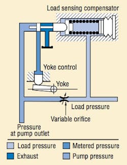
A similar control, which has recently become popular, is the load sensing control, sometimes called a power matching control, Figure 16. The single-stage valve is almost identical to the single-stage compensator control, Figure 12, except that the spring chamber is connected downstream of a variable orifice rather than directly to tank. The load-sensing compensator spool achieves equilibrium when the pressure drop across the variable orifice matches the 300-psi spring setting.
Any of three basic load-sensing signals control a load-sensing pump: unloaded, working, and relieving. In the unloaded mode, the lack of load pressure causes the pump to produce zero discharge flow at bias or unload pressure. When working, load pressure causes the pump to generate discharge flow in relation to a set pressure drop, or bias pressure. When the system reaches maximum pressure, the pump maintains this pressure by adjusting its discharge flow.
Like the pressure-compensated pump, a load-sensing pump has a pressure-compensation control, but the control is modified to receive two pressure signals, not just one. As with pressure compensation, the load-sensing control receives a signal representing discharge pressure, but it also receives a second signal representing load pressure. This signal originates from a second orifice downstream from the first. This second orifice may be a flow-control valve immediately beyond the pump outlet, the spool opening of a directional control valve, or it may be a restriction in a fluid conductor.
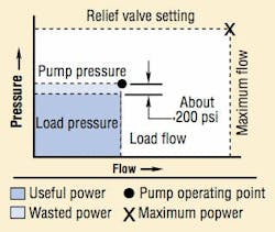
Comparison of these two pressure signals in the modified compensator section allows the pump to sense both load and flow. This reduces power losses even further, Figure 17. Output flow of the pump varies in relation to the differential pressure of the two orifices. Just as the pressure-compensated pump increased its discharge pressure by the amount required to run the pressure compensator, the load- and flow-sensing pump's discharge pressure typically is between 200 and 250 psi higher than actual load pressure.
Furthermore, a load-sensing pump can follow the load and flow requirements of a single circuit function or multiple simultaneous functions, relating horsepower to maximum load pressure. This consumes the lowest possible horsepower and generates the least heat.
Operator Control
If the variable orifice is a manually operated flow control valve, the system can operate in a load-matched mode at the direction of an operator. As he opens the flow control valve, flow increases proportionally (constant pressure drop across an increasing-diameter orifice), at a pressure slightly above load pressure.
As suggested in Figure 17, wasted power is very low with a load-sensing variable volume pump compensator. Since the control senses pressure drop and not absolute pressure, a relief valve or other means of limiting pressure must be provided.
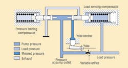
This problem is solved by a load-sensing/pressure-limiting control, Figure 18. This control functions as the load-sensing control previously described, until load pressure reaches the pressure limiter setting. At that point, the limiter portion of the compensator overrides the load-sensing control to destroke the pump. Again, the prime mover must have corner horsepower capability.
Load-Sensing Gear Pumps
Piston and vane pumps rely on their variable-displacement capability to accomplish load sensing. How, then, can a gear pump accomplish load sensing if its displacement is fixed? Like standard gear pumps, load-sensing gear pumps have low initial cost when compared to other designs with equivalent flow and pressure capabilities. However, load-sensing gear pumps offer the versatility of variable-displacement axial-piston and vane pumps but without the high complexity and high cost of variable-displacement mechanisms.
A load-sensing gear pump can:
- provide the high efficiency of load sensing without the high cost associated with piston or vane pumps,
- produce zero to full output flow in less than 40 milliseconds with little or no pressure spiking and without pump inlet supercharging,
- drive circuits with low (approaching atmospheric) unload relief pressures,
- provide priority flow and secondary flow with a low unload pressure to reduce standby and secondary loaded power draw, and
- interchange with load-sensing vane or piston pumps without having to change line or component sizes.
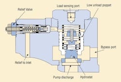
Load-sensing piston pumps use a pressure compensator and a hydrostat to vary volumetric output to a system in reference to load pressure and flow requirements. A hydrostat is a spring-loaded device that meters flow according to the spring force across its equal but opposing effective areas. It may be restrictive, as in a series circuit, or it may bypass primary load pressure to a secondary or tank pressure. In simple terms, a hydrostat separates the total flow into two flows: one represents the required flow and the other represents the required pressure of the primary circuit. A load-sensing piston pump uses its hydrostat to regulate output flow relative to load pressure and bypasses the excess pump flow to a secondary route, which may be ported to tank or to a secondary circuit.
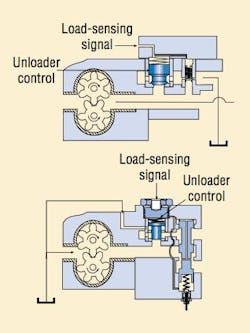
A load-sensing gear pump, on the other hand, uses a hydrostat in combination with an unloader to vary its volumetric output in response to load and flow requirements. Because load-sensing piston and gear pumps both use a single load-sensing signal to control pump discharge pressure and flow, they are interchangeable in load-sensing circuits. Both types have much in common and offer substantial power savings over systems using fixed-displacement pumps. Both offer reduced power consumption in the running mode - when flow and pressure are required to operate a function. They also conserve power in the standby mode - when the system is idling or in a non-operational mode. Furthermore, they can reduce the required size - and, therefore, cost- of valves, conductors, and filters needed for the circuit.
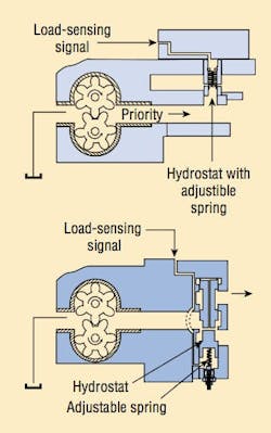
The load-sensing gear pump illustrated in Figure 19 minimizes power consumption in the running mode by separating total discharge flow according to a remote primary function pressure and a primary flow. This is accomplished through a single load-sensing signal originating from the priority circuit and routed as close as possible to the discharge side of the pump's gears.
Adding an unloader control to the pump circuit, Figure 20, allows the system to conserve power in the standby mode of operation as well as in the running mode. This control must be installed in parallel with the inlet port of the hydrostat and as close as possible to the discharge side of the gears. It must be piloted by the same load-sensing signal as in Figure 19. This signal causes the pump to dump all flow from the outlet to the secondary circuit and at a pressure well below the hydrostat's pressure-drop setting in the standby mode.
The unloader control must operate off the same remote load-sensing signal that controls the hydrostat. Unlike the hydrostat, the unloader poppet of the unloader control is designed with opposing areas having a ratio of at least 2:1. Any line pressure sensed that exceeds 50% of pump discharge pressure will close the unloader control. The ability of the unloader control to unload the pump to near atmospheric discharge pressure is controlled by the poppet or plunger spring force. The unloader control is set to the lowest value to maintain the internal pressure loading of the gear pump. When compared to a standard fixed-displacement gear pump circuit, this control can reduce standby power consumption by 90%.
Dual and Combined Controls
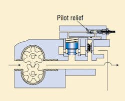
The load-sensing signal can be conditioned by limiting pressure in the remote sensing line or taking it to 0 psig. Doing so causes the hydrostat and the unloader control of the load-sensing gear pump to respond to the conditioned signal according to the discharge pressure. This is accomplished by providing a pilot relief, Figure 21, which causes the hydrostat to act as the main stage of a pilot-operated relief valve. The ability to condition the load-sensing line is patented and makes the load-sensing gear pump useful for functions other than just load sensing.
The combined-control load-sensing gear pump, Figure 22, is intended for large-displacement pumps and bypasses secondary flow to tank. It also is patented, and can be used in the same applications as the dual-control pump. However, because secondary flow must be routed to tank, it cannot be used when the secondary circuit drives a load.
