The problem with valve control of cylinder motion is that it does its work by converting (consuming) unused power to heat in the hydraulic fluid. The advantage of valve control is that it accommodates differential rod- and cap-end flows. Pump control, on the other hand, is efficient because it can deliver power only when and where it is needed. The disadvantage is that it works best with equal area actuators, and works not at all with unequal area actuators.
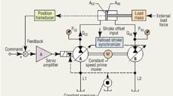
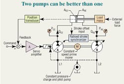
Attempts have been made to use pump control on single-rod cylinders. However, they incorporated some form of valving to deal with the unequal flow, thus introducing an inefficiency. The simplified schematic shown here depicts pump control without any valves, except those needed to control the displacement of the two pumps. This system is called the two-pump control method, and it uses a pump on each end of a cylinder. Put simply, the two pumps have displacements that are matched to the respective cylinder areas. To extend the cylinder, pump A displacement increases to route flow into the cap end of the cylinder. At the same time, displacement of pump B increases to absorb flow from the rod end of the cylinder. Obviously, pump B's displacement must increase at a lower rate than pump A's. This is the function of the block labeled Ratioed stroke synchronizer.
Suppose the cap-end to rod-end area ratio of the cylinder is 2:1. The synchronizer is a mechanism (electrical, hydraulic, or mechanical) that causes pump A's displacement to be twice that of pump B's. If pump A displaces 4 in.3/ rev, pump B will displace 2 in.3/ rev. Clearly, the pumps must be capable of over-center operation. The least expensive means for displacement synchronization would be a simple mechanical linkage between the two pumps. However, the most flexible solution would occur with computer control.
Setting up the system
It would be impractical to try to set up the displacement synchronizer before the system is built. The system can be tuned approximately during final assembly and testing, but the final adjustment has to be done in the system.
The tuning of the synchronizer involves a slight misadjustment of one displacement or the other (it doesn't matter which) to prevent cavitation during system operation. The two pumps must work against each other at all times, but only to a degree. This conflict elevates both pressures, and the adjustment is aimed at ensuring that neither pressure drops below atmospheric, thereby preventing cavitation during normal operation.
How the system works
The circuit in the illustration has the equipment connected in a closed positional servo loop. Preliminary adjustments will set the two displacements at zero when the cylinder is unloaded and not moving. The two cylinder pressures will both be zero, or nearly so. This results in a lack of stiffness in the servo loop — a condition that must be corrected. When the cylinder is at rest, adjusting the offset control causes the displacement of one pump to increase. If this is done to the rod end, fluid from pump B will tend to retract the rod. However, if the piston rod actually does retract, the position loop takes over and increases the displacement of pump A to push the rod back.
The result is that cylinder position is almost completely maintained. However, the pressures at both ends of the cylinder are now elevated. In a 2:1 area cylinder, and with the cylinder at rest with no load, the offset would be adjusted so that the rod-end pressure would be about 2⁄3 of the maximum anticipated pressure, and the cap-end pressure would be about 1⁄3. The elevated pressures deliver the desired stiffness. In fact, it is the same stiffness that contributes to the success of a valve-controlled servo loop. The next step is to tune the displacement ratio synchronizer.
Tuning the synchronizer
Again, the system is to be adjusted with no external load on the cylinder. A command signal is generated — either manually or by some automatic means — to cause the cylinder to extend and retract slowly enough to enable reading and interpreting of the two cylinder pressures. Once the proportioning mechanism synchronizes the two pumps' displacements, the two pressures will change very little as the cylinder extends, retracts, and stops.
To visualize this, imagine a command is given to extend the cylinder, and the displacement of pump B is increasing too rapidly in comparison to that of pump A. Pump B's displacement is moving too much fluid. We would expect pump B's pressure to fall, but so would pump A's. When the cylinder motion is reversed, an excessively high pump B displacement would cause both pressures to increase.
Just the opposite pressure changes will occur if pump B's displacement changes too slowly, or if pump A changes too rapidly. So now the tuning strategy is simple: Adjust the ratio for synchronization until the changes in cylinder pressures between extension, retraction, and stopped are minimized. This will require some judgment because the pressures will not be constant.
The cylinder pressures are determined by a slight mis-adjustment of the offset control — a process made possible by the pumps' internal leakage. The amount of internal leakage resistance determines how much mis-adjustment is needed to reach a given operating pressure. The higher the internal leakage resistance, the less the mis-adjustment.
Because the internal leakage resistance is affected by the internal sealing and clearances within the pump, it is dependent upon manufacturing tolerances. This means one pump pair will require a different offset than another because the tolerances will be different in each pump specimen. This is the reason why final tuning has to be done as a system. Pump ratioing also must be matched to the cylinders.
Assessing internal leakage
The amount of internal leakage can be assessed beforehand by copying the procedures developed for servovalves, namely, by conducting a pressure gain test on each pump. The pressure gain test is conducted by driving the pump from a suitable prime mover, with pump displacement set at zero, and with the pump output port blocked. Then, the displacement of the pump is slowly — but only slightly — increased while the deadhead pressure is measured. A graph of command signal into the stroke controller vs. pump deadhead pressure is the graph of importance.
The test can be repeated individually on each outlet port. The slope of the deadhead pressure as a function of command signal input is the pressure gain. When gain is very high — indicating very high volumetric efficiency — it may be necessary to add an external leakage path from the outlet port. This external leakage path also contributes to system damping, which helps improve the stability of the servo loop. This is also done regularly with servovalve control.
A flow gain test can also be conducted — again, as is done with servo and proportional valves. The pump is operated at nominal shaft speed while the output flow is routed directly to a low-resistance flow meter. The slope of the output flow under zero pressure versus input signal is the flow gain of the pump. The internal leakage resistance is simply the ratio of the pressure gain to the flow gain, provided both tests are conducted at the same shaft speed.
A key parameter is the internal leakage resistance, and, most importantly, how it varies. Pump tests reveal that leakage resistance varies with displacement and somewhat with pressures. This is because clearances can change. For this reason, we can expect the no-load pressures during extension, retraction, and stopping not to remain constant but, rather, to change. The degree of change will depend on the degree to which the internal leakage resistance is not constant. At any rate, the closed-loop pressure testing just discussed will result in a map of the internal leakage resistance of the two pumps as a set.
Clearly, a disadvantage of this system is that two pumps are required for each actuator. Plus, a pair of pumps must be provided for each axis to be controlled. However, as fuel costs approach $4/gal, and perhaps higher, a pair of pumps could become a bargain. This point begs the question, "Will this method work on mobile machinery as well as industrial?" We'll explore that topic — and other viable configurations — in next month's "Motion Control."
Handbook details Electrohydraulic Systems
The Designer's Handbook for Electrohydraulic Servo and Proportional Systems covers electrohydraulic system design, control, and analysis by teaching principles and reviewing practical problems from the real world instead of endlessly discussing complicated theories.
Much of the information updates and expands on important concepts and calculations from such groundbreaking works as George Keller's Hydraulic System Analysis and Jean Thoma's Hydrostatic Power Transmission. The book sells for $99.95, plus shipping and handling. The textbook:
- covers everything from fundamental hydraulic circuit analysis to dynamic testing of motion control systems,
- is packed with more than 500 pages of useful formulas and dozens of fully worked examples, and
- contains 20 chapters covering hundreds of topics, including components, systems, circuit analysis, modeling, servomechanism and control, simulation, and testing.
For more information, including a detailed table of contents describing all topics discussed, visit the H&P Bookstore.


