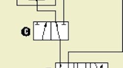
In normal operation, the circuit routes hydraulic fluid at system pressure to motor A through valve C.
For higher pressure, valve C shifts to direct flow to the flow divider (far right). Output flow from the left-hand section of the divider is dumped to tank. Because the two flow divider sections are mechanically connected, the pressure drop across the left-hand section converts the right-hand s ection to a pump. Flow to the motor from the right-hand section is pressure-intensified.
In this simple example, if the two sections of the flow divider have the same displacements (for equal flow), the new flow rate to the motor-will be one half of the original – at double the pressure.
Morgan suggests gerotor flow dividers — such as Roller Stator flow dividers from White Drive Products, Hopkinsville, Ky. — for this circuit because they have a relatively flat efficiency curve across a wide range of flow volumes. (Gear-type flow dividers, on the other hand, have to be designed for a specific flow range because their efficiencies are so dependent on an optimum speed.)
Also, Morgan says, the flow dividers from White Drive Products are structurally tougher than typical gear-type flow dividers and can be ordered with an integral relief valve. Finally, gerotor rotary flow dividers are available with sections that have different displacement ratios, allowing designers to select a variety of flow and pressure combinations to match an application.
As to other components in the circuit, the center position of valve B can be whatever configuration the designer feels is appropriate, or even eliminated. Likewise, valve C could have three positions, if necessary, for some circuit function. The type of valve actuator is inconsequential to circuit performance. And, of course, the type of hydraulic fluid also does not affect the effectiveness of Morgan's circuit.
Contact George Morgan by phone at (812) 476-4065 or by e-mail at [email protected].


