Last month’s edition of “Motion Control” introduced the VCCM equation:
fL = PSAPE –v2(APE3 ÷ KVPL2) (1+ρV2 ÷ ρC2)
where fL is the load force that must be overcome,
PS is supply pressure,
APE is the cylinder size,
v is the speed of cylinder propulsion,
KVPL is the degree to which the valve is open,
ρV is the symmetry of the valve, and
ρC is the cylinder area ratio (cap side of piston area/rod side area).
The pressure drop across the valve is implicit in the equation.
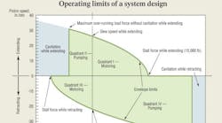
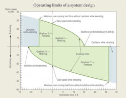
When the VCCM equation is interpreted, evaluated and graphed, the result is the force-velocity operating envelope, shown below. The force-velocity operating envelope describes the operational boundaries for a given cylinder, supply pressure and valve coefficients. The graph can be calculated for any system when the supply pressure, cylinder area, valve coefficient, valve ratio, and the cylinder area ratio are known.
These five parameters are evaluated for single rod-end cylinders under both extending and retracting conditions, then a range of values is selected for the output velocity, v. Next, the load force is calculated using the VCCM equation. When the data points are plotted, the graph displays all four quadrants of cylinder operation:
I. Motoring — The cylinder extends with a load that opposes extension.
II. Pumping —The cylinder extends with a load that assists the extension (over-running).
III. Motoring — The cylinder retracts with a load that opposes retraction.
IV. Pumping — The cylinder retracts with a load that assists retraction (over-running).
The two pumping quadrants are encountered most often when decelerating massive loads. When decelerating a load, the cylinder becomes a pump, converting mechanical load energy into hydraulic energy, which the valve dissipates in its metering lands. If the force required to produce deceleration is excessive, the pressure in the filling end of the cylinder drops below atmospheric pressure, which can cause cavitation. Fortunately, because motion control simultaneously controls acceleration, speed, and position, systems can be designed that avoid cavitation.
Stay in the envelope
Proper system design requires that all necessary operating points lie within the operating envelope. It is normal to seek out the worst cast operating point, usually where the force-velocity product is maximum (maximum power), and ensure that the operating envelope encompasses that point. If that point is indeed the worst-case operating point, then, by definition, all other required operating points are less demanding. Therefore, they must lie within the operating envelope.
The illustration at right represents the limits for a system that is already designed — all components and the operating pressure have been established. At design time, the components and supply pressure must be selected so that the worst-case operating point lies within the operating envelope.
The illustration represents a system that was designed to produce 15,000 lb of stall force and a slew speed of 25.5 in./sec while extending. The supply pressure is 1200 psi, the cylinder has a 4-in. bore, and the rod diameter is 3 in. This produces a retraction envelope with a stall force of 11,250 lb and a retract slew speed of about 23 in./sec.
The maximum over-running load without cavitation while extending is about 6500 lb. But while retracting, the maximum over-running load is about 26,700 lb. This defines the complete operating envelope. Any combination of force and velocity that falls within this envelope can be propelled by the system.
Forces and velocities
Force-velocity combinations outside the envelope cannot be accommodated. The degree of servo or proportional valve opening must be changed to reach force-velocity combinations within the envelope. In manually operated systems, the human operator performs this chore. In a closed-loop motion control system, the servo loop automatically adjusts the degree of valve opening to meet load and command requirements.
The stall force is defined as that force great enough so that the hydraulic force is too low to overcome the load, so the cylinder comes to a stop. Mathematically, it is so great that the speed in the VCCM equation becomes zero. At that point, the entire the velocity term (v2) vanishes, and we are left with the calculated stall force:
fL,stall = Ps × APE
It should be evident that the stall force is nothing more than the entire supply pressure applied to the piston’s powered end area. Further observation reveals that the velocity term represents the loss in cylinder force caused by the pressure loss across the valve lands. In other words, the actual cylinder output force is equal to a theoretical stall force minus that force lost because of the control valve lands.
Also note that as valve coefficient KVPL increases, the loss term decreases. Common practice in conventional hydraulic circuit design is to size the control valve so it exhibits very low pressure drop. This is the same as saying the valve has a high valve coefficient. In such cases, the pressure drop across the valve is small, the force loss is small, and the calculated force merely becomes the supply pressure times the powered end area.
Two different stall force values exist: one for extending and one for retracting. They are important points on the operating envelope. Specifically, they identify the points where the actuator velocity is zero.
Another key point on the operating envelope is the slew speed, which is the intercept on the velocity axis corresponding to zero load force. It can be calculated from the VCCM equation by setting the load force to zero and solving for v.
Solving for v yields two different values, one for extending and one for retracting. An interesting aspect of the slew speed for valve-controlled, single rod-end cylinders, is that slew speed for extension is greater than slew speed for retraction, which is just the opposite of pump-controlled cylinders.
Avoiding cavitation
The last key point on the operating envelope is the condition of impending cavitation. It is found by setting the pressure in the powered end of the cylinder to zero, then solving for the conditions that will produce the condition. In that development, we find that the maximum deceleration force (over-running load) without cavitation is given by:
fL,max = (1+ρv2/ρc3) APE × PS
which applies to both extension and retraction with the proper interpretation of the valve and cylinder ratios. The amount of the overrunning load force must be less than the value calculated in the above equation, because no good comes of cavitation.
But in the world of servo and proportional valve control, if the valve truly controls the flow into the actuator, then the pressure drop across the valve be must be substantial. In fact, in a true valve controlled system, the pressure drop across the valve will normally vary from nearly zero to nearly the supply pressure as the load moves, accelerates, decelerates, and stops. This means that the velocity term (also called the force loss term) cannot be ignored. Instead, it is essential, because it is the means by which the valve asserts its control function into the circuit.
This is the so-called velocity term. It should be looked at in the context of the entire VCCM equation. Note that if velocity, v, is zero, the entire velocity term is zero. That is, at zero speed, there is no pressure loss across the valve’s metering lands. This is not a profound conclusion. Zero speed is also the stall condition, where the load force is so great that system pressure acting on the cylinder area cannot move the piston.
If the load force is relaxed, the speed will increase, and a larger and larger value for the velocity term will be subtracted from the stall force, leaving less force available at the cylinder rod. Note that the velocity term (force loss) increases by the square of the speed.
An interesting side note to the velocity term is its role in conventional” hydraulics. In such scenarios, it is not at all unusual to select valves that have such a great degree of opening that they result in negligible pressure drop. In terms of the VCCM equation and the velocity term, this is a situation in which KVPL is so large as to make the velocity term small. The point is that the VCCM equation is very general and applies both to conventional as well as servo or proportional hydraulics. The bottom line, though, is that with the best valve control that modern technology has to offer — control by means of electrically modulated valves — there must be substantial pressure, force, and power loss to avoid sacrificing good control.
High efficiency and pressure compensation from a fixed displacement pump?
Designing a successful closed-loop electrohydraulic motion control system usually starts with providing a constant pressure source. The traditional solution has been to provide a variable-displacement pump and accumulators in the hydraulic power unit.
You can read about the complete test results, but more importantly, you can learn all you need to design and build your own low cost, efficient constant pressure power units for both servo and conventional applications.
The soft-bound book, ISBN 097022591, contains 128 pages and can be purchased at the H&P bookstore. To ask the author a question about the book’s technical content, email [email protected].


