Bang-bang is the term often used to describe basic directional-control valves. It refers to how the valves shift—from completely open to completely closed. This usually occurs in an instant, causing fluid to rapidly accelerate and decelerate. Under certain conditions, this can cause fluid hammer, which sounds like a hammer striking the hydraulic system from inside. Hence, shifting the valve from one position to another can produce a bang-bang sound.
A less-informal term to describe these components is discrete valves. This term refers to how the valves operate: They shift from one discrete position to another, such as extend, retract, and neutral. Proportional valves, on the other hand, control direction and speed. In addition to shifting into discrete positions, they can shift into intermediate positions to control actuator direction, speed, acceleration, and deceleration.
Even more basic than the discrete directional-control valve is the binary valve. As in digital electronics, binary valves operate either on or off. Whereas discrete valves generally use a spool to achieve two, three, or more positions, discrete valves use a plunger, poppet, or ball that seals against a seat. The advantage to this type of operation is that it provides a positive seal to prevent cross-port leakage.
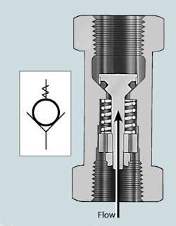
Perhaps the simplest of all directional-control valves is the check valve, a specific type of binary valve. Basic check valves allow fluid to flow in one direction but prevent fluid from flowing in the opposite direction. As with all fluid power components, directional-control valves can be represented by standard symbols published in ISO 1219. Figure 1 shows a cross-section of a spring-loaded check valve and its ISO 1219 representation.
1. Basic check valve allows fluid to flow in one direction, in this case from bottom to top. Shown are ISO symbol and cross-sectional photo of spring-loaded check valve. The spring keeps fluid from flowing unless downstream pressure acting on the poppet overcomes spring force.
Ports and Positions
The two primary characteristics for selecting a directional-control valve are the number of fluid ports and the number of directional states, or positions, the valve can achieve. Valve ports provide a passageway for hydraulic fluid to flow to or from other components. The number of positions refers to the number of distinct flow paths a valve can provide.
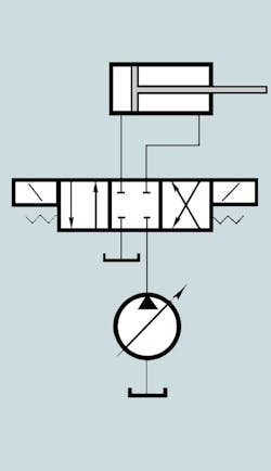
A 4-port, 3-position spool valve serves as a convenient illustration (Fig. 2). One port receives pressurized fluid from the pump, and one routes fluid back to the reservoir. The other two ports are generally referred to as work ports and route fluid to or from the actuator. In this case, one work port routes fluid to or from the rod end of the cylinder, the other routes fluid to or from the cap end.
The valve represented in Fig. 2 can be shifted to any of three discrete positions. As shown, in the neutral position, all ports are blocked, so no fluid will flow. Shifting the valve to the right routes fluid from the pump to the rod end of the cylinder, causing its piston rod to retract. As the piston rod retracts, fluid from the cylinder's cap end flows to the reservoir. Shifting the valve to the left routes fluid from the pump to the cap end of the cylinder, causing the piston rod to extend. As this occurs, fluid from the rod end of the cylinder flows to the reservoir. Returning the valve spool to the center position again blocks all flow. (In reality, a relief valve would be provided between the pump and directional valve. It is omitted here for simplicity.)
2. Schematic shows simple circuit to control cylinder extension and retraction using a 4-port, 3-position spool valve.
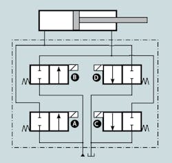
Spool-type valves are widely used because they can be shifted to two, three, or more positions for routing fluid between different combinations of inlet and outlet ports. They are used extensively for directional control of actuators because a single valve can produce extension, retraction, and neutral. However, these same functions can be accomplished with binary valves. Figure 3 shows four normally closed (NC) binary valves grouped into a hydraulic integrated circuit to provide the same functionality as the spool valve represented in Fig. 2.
3. Arranging binary valves into a hydraulic integrated circuit allows them to accomplish the same functions as discrete spool-type valves while retaining the advantages of binary valves.
However, an important distinction must be made between binary hydraulic and electric switches. When an electric switch is closed, a switching element allows electrical current to flow through the switch. When the switch is open, the electrical path is interrupted, so current cannot flow. In contrast, when a hydraulic valve is open, it allows fluid to flow. When it is closed, fluid cannot flow because its flow path is blocked.
With all valves in the neutral condition, as shown, fluid flow to and from the pump, reservoir, and actuator is blocked. Energizing valve A routes pressurized fluid to the cap end of the cylinder, causing the rod to extend. Simultaneously energizing valve D routes fluid from the cylinder’s rod end to the reservoir. In similar manner, energizing only valves B and C causes the rod to retract and routes fluid from the cylinder’s cap end to the reservoir.
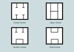
The valves in Fig. 3 are arranged to match the closed-center spool condition of the valve in Fig. 2. An open-center condition (Fig. 4), could be achieved simply by making all the binary valves normally open (NO) instead of normally closed. Likewise, tandem- and float-center configurations can be accomplished by using NO and NC binary valves.
4. Above are common center-spool arrangements for matching neutral-position fluid routes to the application.
These and other common center-position configurations can be quite specialized, depending on the application of the valve. Most manufacturers offer a variety of center-position configurations as standard, off-the-shelf items. Although the vast majority of directional-control valves for industrial applications are 2- and 3-position, many valves used in mobile equipment come in 4-position configurations to accommodate special needs.
When specifying the specific type of valve needed for an application, it has become common practice in North America to refer to the number of ports on a valve as the way, such as 2-way, 3-way, or 4-way. However, international standards use the word ports. Thus, what is known as 2-way, 2-position directional valve in the U.S. is called a 2-port, 2-position valve internationally and can be abbreviated 2/2. The number before the slash identifies the number of ports, and the second number refers to the number of positions.
Spool Valves
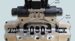
The most common sliding-action valve is the spool-type valve (Fig. 5). Fluid is routed to or from the work ports as the spool slides between passages to open and close flow paths, depending on spool position. Spool valves readily adapt to many different spool-shifting schemes, which broadens their use over a wide variety of applications.
Many mobile applications require metering or throttling to enable the operator to slowly or gently accelerate or decelerate a load. In these instances, the spool may be modified with V notches, for example, so that a small displacement of the spool gradually permits increasing or decreasing fluid flow to gradually speed or slow actuator and load movement. This technique is also used in valves for industrial equipment. A beveled or notched edge on the spool is commonly referred to as a soft-shifting feature.
A variation of the single- or multiple-spool valve is the stack valve, in which multiple spool and envelope sections are bolted together between an inlet and outlet section to provide control of multiple flow paths. In addition to providing a central valve location for the machine operator, the valve grouping reduces the number of fluid connections involved and increases ease of sealing. The number of valves that can be stacked in this manner varies from one manufacturer to another.
Valve Operators
Valve operators are the parts that apply force to shift a valve’s flow-directing elements, such as spools, poppets, and plungers. The sequence, timing, and frequency of valve shifting is a key factor in fluid power system performance. As long as the operator produces enough force to shift the valve, the system designer can select any appropriate operator for the conditions and type of control under which the system will operate.
Operators for directional-control valves are either mechanical, pilot, electrical, and electronic, or a combination of these. Different types of actuators can all be installed on the same basic valve design. A common directional valve often is used that makes provision for mounting a variety of different operators on its body.
With a mechanical operator, a machine element or person applies force on the valve’s flow-directing element to move or shift it to another position. Manual operators include levers, palm buttons, push buttons, and pedals. Purely mechanical operators include cams, rollers, levers, springs, stems, and screws. Springs are used in most directional valves to hold the flow-directing element in a neutral position. In 2-position valves, for example, springs hold the non-actuated valve in one position until an actuating force great enough to compress the spring shifts the valve. When the actuating force is removed, the spring returns the valve to its original position. In 3-position valves, two springs hold the non-actuated valve in its center position until an actuating force shifts it. When the actuating force is removed, the springs re-center the valve, leading to the common identification, spring-centered valve. Detents are locks that hold a valve in its last position after the actuating force is removed until a stronger force is applied to shift the valve to another position. The detents may then hold this new position after the actuating force again is removed.
Mechanical operation is probably the most positive way to control industrial fluid power equipment. If a valve must shift only when a machine element is in a certain position, the equipment can be designed so that the machine element physically shifts the valve through a mechanical operator when the element reaches the correct position. This arrangement virtually eliminates any possibility of false or phantom signals from shifting the valve at the wrong time.
However, mounting mechanically operated valves on a machine requires some special cautions. The valve and actuator may be exposed to a wet or dirty environment that requires special sealing. The actuator will probably be subjected to impact loads, which must be limited to avoid physical damage. Valve alignment with the operating element also is important, so the valve must be mounted accurately and securely for long service life.
Pilot-actuated valves are shifted by pressurized fluid (often about 50 psig) that applies force to a piston that shifts the valve’s flow-directing elements. An important advantage of pilot operation is that large shifting forces can be developed without the impact and wear that affects mechanically actuated valves. Pilot-operated valves can be mounted in any convenient or remote location to which pressure fluid can be piped. The absence of sparks and heat buildup makes pilot-actuated valves attractive for applications in flammable or explosive environments.
Electric or electronic valve operation involves energizing a solenoid. The force generated at the solenoid plunger then shifts the valve’s flow-directing element. Solenoid-actuated valves are particularly popular for industrial machines because of the ready availability of electric power in industrial plants. However, mobile equipment makes extensive use of solenoid-operated valves as well. The selection of ac or dc solenoids depends on the form of electrical power available. At one time dc solenoids offered longer service life, but improvements in ac solenoid designs have eliminated that advantage.
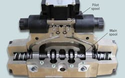
There is a practical limit to the force that solenoids can generate. This means they cannot directly shift valves requiring high shifting forces. Furthermore, valves using large solenoids also consume substantial electrical power when valves must remain actuated for long intervals. Heat buildup can also pose problems in these situations. The solution is to use small, low-power solenoids in combination with pilot pressure. The solenoid starts and stops pilot flow, and pilot pressure provides the high force to shift the valve’s flow-directing mechanism (Fig 5).
5. This cutaway view of a spool-type directional-control valve has pilot valve. When the force needed to shift the main spool of the valve exceeds the practical limit of a solenoid, the pilot valve uses fluid pressure to shift the main spool left or right.
Many valves have combinations of these operators so that the valve can be shifted in response to more than one type of signal. For instance, the solenoid of a 4/3 valve can shift the valve spool in one direction, and a spring would shift it back to the neutral position when the electric signal ceases. Because many valves use more than one type of operator, it is important to determine the role of each. For example, a pilot-solenoid valve may require pilot flow and electrical power to operate. Or it may use either one: solenoid power if an electrical source is available, or pilot operation is the environment must be explosion-proof.
