If you plan on upgrading conventional circuits to hydraulic integrated circuits, be sure to avoid pitfalls that may not be all that apparent.
Integrated circuits are one of the foundations of modern technology. The electronic variety is at the heart of everything from smart coffee makers to supercomputers, and the hydraulic variety is well on its way to becoming equally indispensable across a wide range of applications. Although the comparison may seem a bit forced at first, the similarities between the two technologies and the reasons for their explosive growth over the last few decades are remarkable.
Both, for example, are products of a quest to combine higher performance with improved reliability in ever smaller physical packages. Both seek to achieve these goals by packing more capabilities into individual components while minimizing the size of the physical connections between them. Furthermore, both are well on their way to replacing the older technologies from which they sprang — and for many of the same reasons.
Traditional hydraulic circuits consist of line-mounted valves and other components linked together through tubes and hoses. Sometimes they are attached to a common plate, and other times they are distributed throughout a system.
Designers later began mounting valves onto subplates to make them easier to maintain and change when necessary. Later still, the subplates were bolted to manifolds to create even more compact control assemblies. Connections got shorter, leakage was reduced, and systems became more compact, but everything was still essentially bolted together in an ad-hoc arrangement.
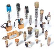
The age of modular circuit designWhile that trend was evolving, a revolution was taking place in valve design. Screw-in cartridge valves made their first appearance on agricultural equipment in the late 1960s. As the name implies, these valves are screwed directly into a manifold, eliminating the traditional cast iron valve body completely. Initially limited to basic functions, cartridge valves quickly grew in performance and sophistication to mirror many of the capabilities of traditional valves.
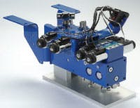
The merging of the two trends is represented by what Eaton calls modular circuit design, a technology that consolidates most or all of the control functions required in a vehicle or device into a single, compact manifold populated primarily by cartridge valves with only a few surface-mounted valves. Other manufacturers have their own terminology, but regardless of what they’re called, these hydraulic integrated circuits are well on their way to becoming the standard solution for hydraulic control systems in the majority of both mobile and stationary applications.
Hydraulic integrated circuits offer several advantages, such as:
• Short flow paths and customized designs can provide higher performance than traditional line-mounted and subplate-mounted systems can.
• Control assemblies are extremely compact, inherently vibration resistant, and highly reliable.
• Installation is simplified because fewer hydraulic and electrical connections are required. Hydraulic integrated circuits often can be attached directly to steering units, pumps, and cylinders to reduce both overall system complexity and installation because fewer connections need to be made.
• Opportunities for leakage are dramatically reduced because all control interconnections and most of the moving valve components are inside the manifold block. Only connections for input and return lines, and links to cylinders, motors, and other actuators are required.
• Identical custom units with specialized capabilities are easily and economically produced in quantity. Mounting, plumbing, and wiring all can be standardized.
• Single-sourcing simplifies procurement processing and reduces overall system costs. This can also mean leveraging complementary technologies, including industrial and mobile valves, fittings, and fluid conveyance to produce cost-effective solutions.
How to go modular
With these advantages available, it’s easy to understand why hydraulic integrated circuits have steadily grown in popularity. However, many traditional line-mounted, and transitional subplate/manifold systems are still in use, so managing the transition to a modular system is critical to its success.
A circuit designer’s first impulse often is simply to duplicate an existing traditional system as a modular one. If the original circuit consists only of simple check and relief valves, this approach may suffice. But if you are updating a line-mounted system and enhancing its performance with electrohydraulic proportional valves or load-sensing priority flow regulators, the do-it-yourself approach will likely be a mistake. Much more is involved in making this kind of change than simply substituting new components for the old ones.
For example, the shorter, more efficient flow paths of the hydraulic integrated circuit will inevitably alter the response and performance of other system components. Sometimes the changes are subtle, and sometimes they are not, but either way, they must be anticipated and accounted for.
Internal flow paths also impact performance. If you place a pressure port so it restricts flow to a flow divider, the result may be an underperforming device. The relative locations in a line-mounted system might not be as critical, or may simply be masked by other losses. But the very process of making the hydraulic integrated circuit more compact can sometimes magnify the impact of even the smallest details.
There’s nothing like experience
The answer to these, and many other potential pitfalls, is to work with an experienced engineering team thoroughly familiar with the intricacies of hydraulic integrated circuits. Yes, you could do it yourself, but the odds are you will get a better result by letting an expert handle the task.
Even then, some guidelines will help ensure a successful outcome. Perhaps the most important of these is to have realistic expectations about what can be achieved with an integrated circuit.
• A sophisticated, multi-function, high-pressure, high-flow system is not going to work if the specifications call for it to be crammed into a shoebox-sized block of aluminum.
• Ten or 15 valves won’t fit in that shoebox, no matter how clever the designer.
• A 1-in. port requires a certain amount of material, and the equivalent performance can’t be achieved with a …-in. passage, no matter how convenient that would be.
• A valve that needs to be “burped” at machine startup must be on top of the manifold block, period.
• If the system will operate at 5000 psi, the manifold block must be steel, regardless of how light you would like it to be.
This all may seem obvious, but every engineer who works with hydraulic integrated circuits can recount real-life instances of each of those examples, and many others as well. The best advice in this regard is to talk to the application engineer and designer early in the development of your hydraulic system.
Eaton and other suppliers have teams of application and product engineers and hydraulic integrated circuit designers dedicated to providing comprehensive support over the life of the application. The more often a supplier team deals with the intricacies of integrated system design, the more likely they are to produce an efficient solution to your requirements.
What they absolutely need to know is how the machine will be used, and what kind of environmental conditions to expect. There is a world of difference between mounting a manifold in the cab of a logging vehicle where it may well be underwater occasionally, and attaching it to a precision machine tool working in an air-conditioned shop. Both may be excellent candidates for a hydraulic integrated circuit, but the systems themselves will be very different.
The more accurately you can define what the system is expected to do, and what the machine it is controlling is expected to do, the more likely you are to achieve a successful result. Hundreds of decisions must go into a successful integrated circuit, and there is no substitute for getting an experienced engineering team involved early in the project. Give them the information they need and let them do what they do best. You will like the result.
For more information, contact the authors directly at [email protected] or [email protected], or visit www.eaton.com/hyd.
Manual lever valves simplify manifold blocksThey replace pull- and push-to-shift, 3-position, 4-port, tandem center, mobile sectional, and manually-operated industrial manual valves and come in open center, closed center, tandem pool, and motor spool configurations. An open center in the motor spool permits a motor to freewheel when the valve is centered, rather than being brought to a stop. Motor spools provide directional control of free-moving cylinders when not being extended or retracted.
Screw-in valves for harsh environmentsClick here for more informaiton on cartridge valves from Eaton Hydraulics.


