Efficient, reliable equipment operation is a must within the harsh environments of wood processing, where components are deluged by dust, taxed by temperature fluctuations, and vexed by vibration and shock. Now more than ever, original equipment manufacturers (OEMs) and wood processors place greater emphasis on the higher performance and lower total cost of ownership of their automated equipment. As a result, pneumatic components are gaining wider acceptance as being rugged enough to withstand these harsh conditions at competitive costs.
Pneumatics in action
Pneumatics can be used in the entire wood processing sequence, from felling the trees to the end product made of wood. Examples of pneumatic advances in wood handling, chipping, and grinding include pneumatic cylinders with special metal scrapers, high temperature seals, and flow control valves, as well as pneumatic manual and mechanically actuated valves used in high-temperature areas.
Highly automated processes have been introduced, such as saws that automatically clamp and saw logs. These saws can cut up to 20 logs per minute, depending on their size and wood species.
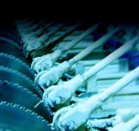
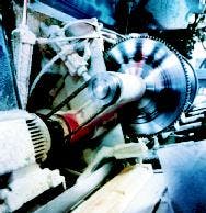
Pneumatics also is used in chop saw applications where severe vertical movements routinely raise and lower saw blades to cut lumber of varying thickness to specifications. Chop saw is a general term for circular saws used to cut to length or trim wood products. Chop saws usually are ganged together across a wide conveyor. The vertical position of each saw is controlled by a pneumatic cylinder to match the saw with line speed.
All of these operations are noisy and occur in a dirty environment, yet pneumatic cylinder and valve combinations on each blade assembly provide high-speed, controlled blade movement. Therefore, pneumatic systems often are chosen for the cushioning effects they can produce, especially with aluminum cylinders.
Aluminum has been gaining favor over traditional steel as the material of choice for components where low inertia is important. In general, familiarity with aluminum and other lightweight materials is growing. This provides pneumatics with a greater influence in this industry because pneumatic components make such extensive use of aluminum and capitalize on its benefits.
Lumber well suited to pneumatics
Compressed air quality has advanced substantially throughout the lumber processing industry, with more sophisticated and precise filtration and valve systems that perform well in hostile environments. When extremely high forces are required, hydraulics still may be the technology of choice, such as in the logging and laminating areas of production. However, in nearly all other areas, pneumatics and hydraulics often work side by side, while pneumatics continues gaining popularity due to advances in electronic controls and hardware.
A pneumatic tie-rod cylinder, for example, may range in bore size from 32 mm to 320 mm. Standard features can include cushioning at both end caps, as well as noise reducing bumpers and magnetic pistons for position sensors. Other options run the gambit from screw-in bushing and wiper combinations to linear guides, high temperature materials, non-rotating piston rods, and piston rod locking brakes.
Air pressurized to 150 psi at temperatures from 5° to 158° F is commonplace, with localized areas approaching 250° F. With proper cushioning, these aluminum cylinders can eliminate the need for expensive industrial steel cylinders in many applications.
Challenges of proportional pneumatics
Generally, closed-loop pneumatics control position, speed, force, and torque on a given lumber processing line. Because sophisticated electronics are required, closedloop electropneumatic control systems can be more costly than with other technologies. However, this higher cost often is offset by cost savings for components, materials, and manpower, and an increase in production.
Ideal pneumatic cushioning
Cylinder cushioning often is viewed as a low-tech method of decelerating a piston as it approaches the end of its stroke. Although it is much less complicated than sophisticated electronic deceleration controls, cushioning can be adjusted to achieve not only less noise and vibration, but shorter cycle times and longer cylinder life as well. When this occurs, ideal cushioning has been achieved.
With ideal cushioning, the piston decelerates from maximum speed to zero without changing direction of travel, so no end-of-stroke bounce occurs. Ideal cushioning requires measuring piston velocity in both directions, which is simplified by an electronic meter. Speeds are then adjusted to conform to a maximum speed for a given pressure and cylinder load.
The specific steps include:
- Measure piston velocity and ensure it corresponds to specificationspublished in manufacturer's literature (such as Bosch Rexroth's Ideal Cushioning charts).
- Adjust the piston velocity accordingly. This is done, typically, by using a screwdriver to adjust flow control valves located in the connection ports of the cylinder. This allows free inlet flow.
- Adjust the outlet pressure by altering the area of the exhaust port with the adjustment screw.
- Use a speed meter (such as Rexroth's MecSpeed) to measure the actual piston velocity after making flow and pressure adjustments. In the past, this had been done by guesswork or by eye. However, because the magnetic piston of a pneumatic cylinder can be detected through its aluminum tube, attaching an electronic instrument to the outside of the cylinder tube makes for easy and accurate electronic speed measurement.
Efficient cushioning is essential in high-speed applications, and most applications can benefit from some form of cushioning to reduce piston speed before it strikes the end cover. Reducing the piston velocity at the end of its stroke lowers the stresses on the cylinder and reduces vibration in the overall structure. The noise from piston-toendcover contact is negligible and the total cycle time is shortened. Thus, properly adjusted pneumatic cushioning can have positive effects on both the working environment and on the cycle time.
Ideal cushioning has been used successfully in sawmills and other wood industry applications to reduce cycle times of bin sorters, trim saws, waste gates, and more. A sawmill facility in the Northwest, for example, recently increased the speed of its bin sorter line 35% by applying the principles of ideal cushioning. Moreover, just about any industrial application where high speeds and smooth, quiet operation are required can benefit from ideal cushioning of pneumatic cylinders.
Click here to download a PDF describing ideal pneumatic cushioning in greater detail.
The best drive for the machine
Although pneumatics typically is the technology of choice for applications such as material handling and small parts assembly, new capabilities, such as closed loop control, precision pneumatic components, and high speed electronics have made these systems more competitive with electrical and hydraulic closed loop systems. Ultimately, though, specifying pneumatic, hydraulic, or electromechanical drives — or any combination of them — where each is most appropriate, provides the flexibility to design the best drive system for any machine.
Ceramic solution provides performance benefits
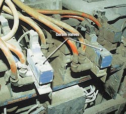
It's a dirty job — Ceram valves use sliding ceramic plates to control compressed air flow and direction, which eliminates potential problems with spool valves. Perhaps more importantly, the ceramic plates allow the valves to be rated for hundreds of millions of cycles.
Pneumatics technology has developed with the pulp and paper industry to make its own contributions, especially in the area of valve technology. In all phases of pulp and paper production, one of the most successful products Bosch Rexroth provides is the Ceram pneumatic directional control valve. The first valve to use sliding ceramic plates for basic sealing functions, the Ceram valve has gained extensive use in the industry, with an expected service life in excess of 150 million cycles.
The valve's ceramic plates allow it to withstand harsh environments and less than perfect compressed air conditions — shrugging off contaminants that could cause other valves to stick or fail. With the Ceram valve, no gap exists between the plates for contaminants to accumulate. In contrast, spool valves may have small gaps that can accumulate dirt, causing sticking or air leakage. Moreover, elastomer seals can deteriorate and wear over time, limiting valve life.
Plates in the Ceram valve have a polished finish and act like sliding magnets, and solenoid operators of the same voltage on standard valves are interchangeable between all sizes, reducing spare parts inventory and downtime. Also, the tight shut off with Ceram valves eliminates air leakage that can occur with other designs.
From a control standpoint, the Ceram valve accommodates serial link connectivity via contact bridges, allowing use of the extensive serial link options. The contact bridges mounted on the solenoid coils allow the valve to be controlled by all major protocols and reduce wiring and troubleshooting time.
Although this valve has proven itself in the wood processing industry with maintenance savings and lower replacement costs, it is also prevalent in other industries such as foundries, steel plants, automotive assembly, and others where life and reliability are critical.
Click here to download a 12-page PDF detailing cylinder cushioning.
Michael Pesano is with Bosch Rexroth Pneumatics, Lexington, Ky. Bosch Rexroth Pneumatics is now Aventics; visit www.aventics.com/us for more information.


