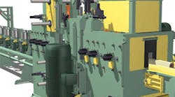
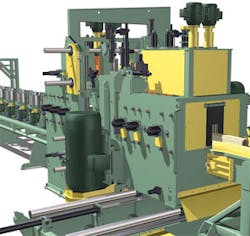
interior view of the machine is shown on the cover of this issue). In feed rollers are shown
at left. In the machine, multiple saw blades spin on a vertical axis that is moved hydraulically
to cut curved lumber along its axis of curvature.
Rotational motion abounds in machines employing fluid power. Typically, rotational motion axes are used for powering material transport (e.g., conveyors) between processing stations. An example of a motion system that employs both linear and rotary motion is the vertical shape saw machine in Figure 1.
Often, rotational axes in machines with hydraulic cylinders are driven by hydraulic motors. Even when they’re driven by electric motors, you should understand the issues associated with rotational axis control. For example, often you must synchronize, or gear, the motion of a conveyor with that of a processing station that has linear actuators (e.g., varying the speed of the log feed chain to match the speed of log cutting in the shape saw example).
Rotary applications, such as conveyors or feed chains — especially those involving electronic gearing — can benefit from the use of feedback devices to provide position information or for reference tracking. While hydraulic cylinders typically use linear feedback devices — such as magnetostrictive linear displacement transducers, MLDTs — rotary axes are typically equipped with rotary encoders for position feedback. As automated machinery becomes more complex, those working in fluid power may see a rotary control application being added to the project list along with the familiar linear axes. This article is intended to provide a practical understanding of using encoders for rotary position feedback. Encoders come in two general categories, incremental and absolute, both of which will be discussed.
Incremental encoders
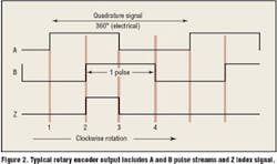
Incremental encoders, which are common in motor control applications, are sensors that output changes in position one pulse at a time. A counter in a PLC or motion controller is used to keep track of the position by counting these pulses. A quadrature incremental encoder sends two pulse streams, A and B, which are 90° out of phase to each other (Figure 2). The relative phase between these two streams changes with the direction of rotation and tells the counter whether it should be incrementing or decrementing.
Incremental encoders are usually specified as having a certain number of lines, or pulses, per revolution but this is just for one of the phases. Standard practice is to count the rising and falling edges of the two pulse streams rather than just counting pulses. Counting these edges, Figure 2, achieves a position resolution of four times the line resolution. In addition to the two A and B pulse streams, a Z index output normally pulses only once per revolution and often is used in homing.
Homing is required
Incremental encoders have one major disadvantage relative to absolute encoders. On power-up, the true (absolute) position of the axis cannot be determined from the A and B pulse streams, so a homing routine is required to initialize the position counter. If the encoder loses power while the system is moving, the counter loses track of the position until power is restored and the axis is homed again. This can be a big problem, for example, in a lumber sorter. Once power is lost, all the lumber on the conveying system must be run off and resorted. In other applications, work in process may have to be scrapped.
Homing on rotational applications can generally be accomplished by rotating the motor slowly until the controller’s home input is activated. Ideally, the Z pulse from the encoder would be used along with a home switch to obtain a precise home position. However, this is not possible in applications where the motor does not turn a whole number of times per machine cycle. In this case, the Z pulse will occur at a different position after the home switch is hit each time the machine is homed. This makes the Z pulse unusable as a homing indicator. To rely solely on a limit switch for homing means that the axis must be moved very slowly during homing operations so that the home switch response time doesn’t greatly affect the home position.
Some situations may require homing on every cycle. This is to correct for noise or other problems with the encoder signals or because the number of encoder counts per cycle is not a whole number of counts.
Absolute encoders
Absolute rotary encoders provide true position information as soon as they are powered up. Using an absolute encoder eliminates the need for initialization. This is preferable when the instantaneous location of the axis is needed, and it is not feasible to perform a homing operation.
Two main types of interfaces to absolute encoders are parallel and SSI (Synchronous Serial Interface). With a parallel interface, the data is transferred all at once — over as many wires as there are bits of data. This has the advantage of being very fast, but it requires many wires. If differential signaling (which doubles the number of wires) is not used, the data are susceptible to corruption from electrical noise.
With an SSI interface, the position information is read from the encoder — one bit at a time — using a single pair of wires for the data, plus a pair for a synchronizing clock signal. The SSI interface is efficient in terms of the number of wires it uses, and the data are not easily corrupted with electrical noise because the interface uses differential signals. The disadvantage is that it takes much longer to read the data out of the encoder.
For example, with an absolute encoder with 25 bits of resolution and a 200 kHz interface rate, it takes more than 125 μs to read the position. For many applications, this delay will not cause any problems, but the extra delay could cause a noticeable decrease in axis performance for certain highspeed applications.
A multi-turn encoder is required if absolute rotational position information is needed for more than one turn of the encoder. Generating 24 bits for rotational position feedback is very common in applications where a motor is moving a chain or cable connected to a load that must travel distances in excess of the one turn of the spool or pulley. The lower 12 bits are used to determine the angle or position within a revolution, and the upper 12 bits are used to keep track of how many turns have been made. Often, the upper and lower bits can be used in a similar way as the 24 bits of position from a SSI linear MDT. This setup can provide very fine resolution.
In some cases, two encoders are used. An absolute encoder is used to set the initial position at power up and an incremental encoder is used during operation because it updates it position quicker or may have finer resolution.
One of the largest sources of error can be caused when reading encoders with low resolution output, which may lead to a noticeable quantizing error. Since the output from an encoder is inherently stair-stepped (i.e., digital rather than analog) it is best to minimize this measurement error by making the steps as small as possible by using a high resolution encoder. Filtering techniques can also be used to minimize the adverse effects of a quantized output (see sidebar at left).
Which one to choose?
Maintaining precise position or velocity control in rotary motion applications can be easier when using a suitable encoder with adequate resolution. Some practical application tips can help as well. For example, some rotational positioning applications are better treated as linear applications as long as the positions don’t increase beyond the range of the counter. If the position counts exceed the counter range, they could roll over, causing the counter to reset to zero. Because the resolution of absolute encoders is usually a binary number, programming rotary positioning applications is easier when there is a power-of-two ratio of encoder turns to load turns.
Absolute encoders have an advantage over incremental encoders because the position is immediately known on power up. They need only be homed at the time of installation while incremental encoders need to be homed at least every time power is applied, and in some cases, as often as every machine cycle. On the other hand, incremental encoders can be better for high-speed applications. However, most hydraulic applications move large masses at modest speeds, so absolute encoders are more than fast enough. And when moving large masses, it is good to know where the load is, right from the start!
For more information, email the author at [email protected].
Computing velocities from encoder data
A common use for encoders in conveyor applications is to calculate line speeds for display or even as feedback for a PID closed-loop control system. Calculating the speed in terms of encoder counts per second is straightforward:
Velocity (counts per sec) = number of counts time between readings
However, it is generally much more useful to express velocities in terms of engineering units such as rpm, inches per second or feet per minute. This can be done by multiplying the velocity in counts times a scale factor:
Velocity (engineering units) = scale velocity (counts per sec.)
The scale can be derived from the system mechanical information and appropriate conversion constants. Example: We need to know line speed of a conveyor in ft/min. Given: Encoder with 2000 lines (8000 counts) per revolution on a 6-in. diameter roller. Controller update time = 1 msec. Assume we read 25 counts in one update time.
Velocity (counts per sec.) = 25 counts 0.001 sec. = 25,000 counts/sec.
Convert to feet per minute. First, find the scale factor. Velocity (fpm) = 0.011781 25,000 counts/sec = 294.5 fpm
One interesting item to note is the minimum velocity increment that can be measured with the system described
above. If we record only one count in a given update period we obtain:
Minimum measurable velocity = 1 count/msec = 1000 counts/sec = 1000 0.011781 = 11.781 fpm.
This is not very good resolution. Note that if the true line speed is 300 fpm in the example above, sometimes we would read 294.5 fpm and sometimes 306.3 fpm, but never exactly 300 fpm. This effect is referred to as quantizing noise or jitter.
To increase the velocity measurement resolution, we can increase the encoder resolution, increase the time between encoder samples, or add a filter to the velocity. There are practical limits to the encoder resolution that can be used, and it may not be desirable to increase the sample time because it can have an adverse effect on the controllability of the axis. That leaves us with filtering the velocity measurement.
The two most common types of digital filters (filters that can be implemented in a microprocessor) are finite impulse response (FIR) filters and infinite impulse response (IIR) filters.
FIR filters take a weighted average of a certain number of readings from the encoder. How the filter behaves depends on the how many readings are used, and how each of the readings is weighted. One disadvantage of these filters is that they require storing as many readings as needed for the averaging in memory. They can also be inefficient to implement if the weighting on all the readings is not uniform, but uniform weighting means newer readings are not given more importance than older readings.
IIR filters continuously update the filtered reading by adding a fraction of the new reading to the filtered value and removing a fraction of the old filtered value:
NewFilteredVelocity = K LastFilteredVelocity + (1 K) NewVelocityReading
K is a value between 0 and 1. If K = 0 there is no filtering, and if K = 1, the filtered velocity is never changed. Under most conditions K is made a little less than one and is adjusted until the desired amount of filtering is obtained. If K is used as a parameter it is best that K is calculated in terms of a frequency response or time constant. In this case,
K = e-2πfT or K = e-T/Γ
Where: T is the sample time
f is the corner frequency or -3db point.
Γ is the filter time constant (1/2πf).
By adding more filtering (making K close to zero) the effects of quantizing noise can be reduced, but filtering adds a delay so you can miss rapid changes in the velocity.


