Compressed air is suitable for low power systems, but air compressibility makes it difficult to control actuators smoothly and accurately. Some low power systems need smooth control, rigidity, or synchronization capabilities normally associated with oil hydraulics. All of these features are available to low power circuits by using compressed air as power and oil for control. Purchased or special built air-over-oil circuits provide smooth control when power requirement is low.
Some manufacturers make self-contained air-powered cylinders with built-in oil cylinders and reservoirs. Air provides thrust while oil controls speed and/or mid stroke stopping. Some units have two speed capabilities as well as stop and hold options. ARO Corp.’s "Coaxial Cylinder” and Schrader Bellows’ "Air Motor-Hydro-Check" are two such units. Both of the above companies also make a bolt-on control unit that mounts on a standard air cylinder and controls speed and/or position.
Coupling low-pressure hydraulic cylinders with air-over-oil tanks is another common way to create an air-over-oil system. These tanks hold more than enough oil to stroke the cylinder one way. Having an air valve piped to the air-over-oil tanks forces oil from the tanks into the cylinder. Add flow controls and stop valves to the oil lines to give smooth accurate cylinder control. Air-over-oil tanks do not intensify the oil, no matter the tank diameter or length. The amount of air pressure supplied is the highest possible oil pressure available.
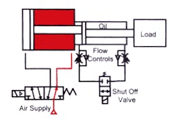
Tandem cylinders can also control oil and air power. The single-rod cylinder of the tandem runs on air, while the double-rod cylinder is full of oil. Because volume is equal in both ends of the double-rod cylinder, oil flows from end-to-end through flow controls and/or shut off valves for accurate speed and stopping control.
When designing with air-over-oil systems, take care sizing the oil lines. Most air-oil circuits operate at 100 psi or less, so any pressure drop in the circuit can reduce the force drastically. If oil lines are undersized, cylinder movement will be very slow. Size most air-over-oil circuit oil lines for about 2 to 4 ft/sec velocity. This low speed requires large lines and valves but is necessary if average travel speed with maximum force is important.
Bleeding of air from the oil chambers can present another common problem with air-over-oil circuits. Any trapped air in the oil will make the cylinder spongy. This compressibility makes accurate mid-stroke stopping and smooth speed control hard to attain. When using an air-over-oil tank system, it is best to mount the tanks higher than the cylinder they feed. All lines between the cylinder and the tanks should slope up to them. Also, if possible, let the cylinders make full strokes to purge the air. With dual oil tank systems, incorporate a means for equalizing tank level in the design.
The cylinder seals must be as leak-free and provide the lowest amount of friction as possible. Any leakage past the seals can cause tank overflow, oil misting, and loss of control. The following examples can be used to provide low power with smooth control rather than oil hydraulics.
Be sure to read Chapter 13 on Intensifiers to learn more about air-over-oil circuits that also require short, high-force work strokes.
Air-over-oil tank systems
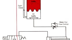
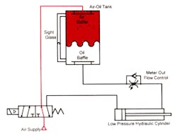
Figure 3-1 shows a single tank air-over-oil system with an air valve piped to an air-over-oil tank to power the rod end with its other port connected directly to the cylinder cap end. A flow control valve in the oil line controls the cylinder advance speed. The cylinder’s extend speed is very slow and controllable with this setup. Also, external forces trying to extend the cylinder cannot make it move faster than the flow control allows. If force requirements keep changing while the cylinder is moving, speed will change very little as long as the cylinder has enough force.
Leakage of air past the piston seal can be a problem in a single tank air-oil circuit. Any air mixed with the oil can cause erratic movement and reduced cylinder control. Oil leaking past cylinder seals can cause misting and the environmental problems associated with it.
This circuit is good for replacing a straight air cylinder that is moving a large load. When load force requirements on the extend stroke are variable, a straight air cylinder may stop or lunge uncontrollably. With oil in the rod end of the cylinder, movement will be smooth. Even if the cylinder stops, it will not lunge when it starts again.
Notice the baffles in the air oil tank. The top baffle keeps incoming air from shooting into the oil, causing aeration. The bottom baffle stops any vortexing that might allow air to enter the cylinder as the tank level lowers.
Sight gauges are also necessary to monitor oil level on the air-over-oil tank. Purchased air tanks usually come with baffles, sight gauges, and a fill port. Some purchased air-over-oil tanks feature air cylinder tubing with two cylinder caps held in place with tie rods. Air-over-oil tanks should be sized to run approximately 75% full for optimum performance.
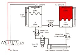
Figure 3-2 shows a double tank system. Two tanks eliminate the aeration problem caused by leaking cylinder seals. They will also allow accurate flow or stop control in both directions of travel. A twin tank system is more expensive, and may slightly reduce maximum cylinder speed.
When using two oil tanks, always put a line with an equalizing valve between the tanks. This line should be below the lowest tank oil level to allow easy adjustment of tank oil level when cylinder seals bypass.
When filling air-over-oil tanks, stroke the cylinder toward the low one. This action exhausts the tank's air for fill-plug removal and allows replenishing without overfilling. Also, it traps minimal air in the piping and the cylinder. Never fill a tank to capacity when the cylinder is stroked away from it. If oil gets into the cylinder as well as the tank, it will overflow as soon as the cylinder strokes.
Install a solenoid or pilot-operated shut-off valve in the oil lines to the cylinder for accurate control. A shut-off valve makes it possible to precisely position and hold the cylinder for long periods. Since oil is practically non-compressible, a cylinder will not move even if outside forces push against it. If excessive outside force is possible, install a relief circuit to protect the cylinder and machine structure. Tandem cylinders in air-over-oil circuits.
Continued
Figure 3-3 shows a tandem cylinder piped for speed control and mid-stroke stopping. A tandem cylinder unit provides the same results as an air-over-oil tank system. An air valve piped to the single-rod cylinder gives directional control. Install meter-out flow controls and a shut-off valve in the line between ports on the double-rod cylinder. The double-rod end cylinder is completely full of oil and sealed against leakage. A small makeup tank attached to the transfer line, with a check valve between it and the cylinder port, allows oil to enter the cylinder when needed.
This tandem cylinder arrangement operates smoothly and gives accurate mid-stroke stopping control. A tandem cylinder is about the same price as a dual tank system. However, space requirement at the workstation more than doubles. Also, long-stroke tandems can be hard to mount and maintain. Normal piston seal leakage is no problem, but rod seal leaks can let oil out and/or air in, causing a house keeping problem and spongy cylinder movement.
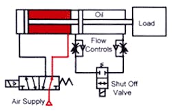
Figure 3-4 shows a large-bore, high-force air cylinder with a small-diameter hydraulic cylinder in tandem with it. An unmatched tandem cylinder has ample oil for smooth control and/or precise positioning. Unmatched tandems offer two big advantages: less cost and lower oil flow.
When specifying unmatched tandem cylinders, make sure the piston rod sizes are compatible between the air and oil cylinders. Rod size usually dictates the smallest bore hydraulic cylinder possible. Also, check for excessive pressure in the oil cylinder that could damage it and flow-control or stop valves. The higher oil pressure comes from intensification due to different bore sizes. Also, a vertically mounted cylinder with a heavy load adds load-induced pressure to intensification, possibly damaging components rated for air or low-pressure hydraulic service.
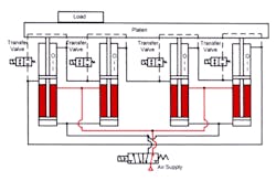
Figure 3-5 shows an accurate way of synchronizing two or more air cylinders with fluid power. Four tandem cylinders are hooked to one platen, which will stay level throughout the stroke. Force from all four cylinders is available to move the load, regardless of its position.
Notice the transfer valves between the tandem cylinder’s cross port lines. Always return a fluid-type synchronizing circuit to a positive home position often, preferably after every cycle. When the air cylinders return the platen to home position, the transfer valves open to allow the cylinders to resynchronize. Doing this after each cycle eliminates any cumulative position error from seal leakage.
When using unmatched tandem cylinders in a synchronizing circuit, check for overpressure from intensification and load-induced pressure as mentioned above. Placing a heavy load over one cylinder provides pressure intensification from the other actuators. All other cylinders will transfer their excess energy through the oil lines to the loaded cylinder. The loaded cylinder would then be capable of pushing with four times its normal force. One-fourth of this force would be from its own air cylinder, while three times more force comes from energy transfer. This could overpressure the cylinders or valves, causing failure.
Figure 3-6 shows opposing tandem cylinders. These cylinders will meet exactly in center. Drilling a center hole in odd sized parts is one possible use for this circuit.
