Hydraulic Sensors: Understanding the Types and Integration Strategies
What You’ll Learn
- The types of sensors commonly used in hydraulic systems for both mobile and industrial applications.
- How data gained from sensors can benefit hydraulic system performance and maintenance.
- Methods for integrating sensors into hydraulic components and systems.
Across industries — from construction equipment and offshore drilling rigs to steel mill presses and injection molding cells — there is a realization of the benefits sensors can provide to the hydraulic systems used in these applications.
Mechanical and electrohydraulic fundamentals haven't changed much in decades. But the ability to instrument those systems to pull granular, high-speed data from every critical node has transformed how hydraulic systems and machines are designed, operated, and maintained.
Read part two of this article series on sensors for hydraulics, "How Sensor Technology is Improving Performance in Hydraulic Systems" to learn more about the performance benefits sensors are bringing to hydraulics.
In this first of a two-part series on hydraulic sensors, we walk through the sensor technologies driving this transformation. We'll cover the specific types of sensors used in hydraulic applications, the information that can be gained from these sensors, as well as how they're integrated into components such as pumps, valves, cylinders, and manifolds.
The Core Sensors Used in Hydraulic Systems and What They Actually Measure
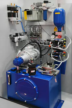
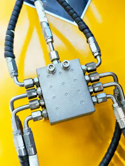
There are a range of sensors which can be integrated into hydraulic components and systems. Pressure, flow, temperature as well as level and contamination sensors are among those commonly used within these systems.
With these sensors machine owners can gain a wealth of information about the performance of their hydraulic systems and the machines into which they are integrated, aiding maintenance and other operational efforts.
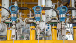
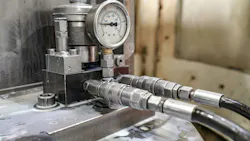
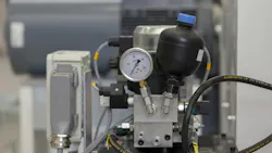
Pressure Sensors: The Heartbeat of the Circuit
Pressure is the primary variable in any hydraulic system, and modern pressure sensors have become extraordinarily capable. Piezoresistive sensors where a silicon or thin film strain gauge changes resistance under applied pressure can cover a wide hydraulic pressure range, often exceeding 50 bar and reaching much higher depending on the design, with accuracy varying by sensor type. That's useful for steady state monitoring, but the more interesting capability is dynamic response.
High-speed pressure sensors with a frequency response up to 20 kHz can capture pressure transients that would be completely invisible to conventional instrumentation. Cavitation can create abnormal pressure fluctuations, and a sensor mounted near the pump inlet that logs pressure transients can help detect cavitation-related issues before major damage occurs.
In practice, monitoring pressure patterns across a pump can provide an early indication of cavitation, but the lead time depends on the system and operating conditions.
For servo valve applications, pressure feedback loops have become standard in precision motion control. A proportional valve with integrated pressure sensors on both work ports can support closed-loop pressure control in precision hydraulic motion systems. The hydraulic system's raw power density stays intact; sensor-driven control adds the precision.
One practical point on placement: avoid mounting pressure sensors in dead-end fittings where trapped air can compress and distort readings. Flush-mounted diaphragm designs, where the sensing element is exposed directly to the fluid, eliminate that problem.
For high-vibration environments, such as mobile equipment and hydraulic presses, select sensors with a natural frequency well above the dominant mechanical vibration frequency of the structure they're mounted on.
Flow Sensors: Where Energy Savings Get Quantified
Flow measurement in hydraulic circuits historically meant adding a test point and temporarily connecting a handheld flow meter. That gave a snapshot, not a trend.
Permanent flow sensors change the picture entirely. Turbine flow meters, gear-type flow meters, and Coriolis-effect devices all have established places in hydraulic systems, each with tradeoffs in accuracy, pressure drop, and compatibility with viscous oils.
Turbine flow meters are the workhorse for mid-range flows, typically 0.5- 500 L/min, with accuracy of ±1% of reading when calibrated for the actual fluid viscosity. Gear-type positive displacement flow meters offer higher accuracy down to ±0.1% and work better with viscous fluids like ISO VG 68 or VG 100 hydraulic oil. The tradeoff is a small but real pressure drop, typically 0.3-0.8 bar at rated flow.
For highly viscous fluids, some cutting oil and water-glycol systems run kinematic viscosity above 100 cSt. Ultrasonic clamp-on flow meters offer a viable option with zero pressure drop and no wetted parts to contaminate. However, accuracy degrades compared to turbine flow meters (typically ±2 to 3%), but for trend monitoring and gross efficiency calculations, that's often sufficient. The installation advantage of no pipe cutting and no downtime makes them attractive for retrofit applications.
The energy savings case for flow sensing is concrete. Variable displacement piston pumps, controlled by pressure-compensated flow matching, are efficient when properly tuned. But without real-time flow feedback, pump displacement often runs higher than necessary to maintain a pressure margin.
Installing flow sensors in the main supply and return lines allows a PLC (programmable logic controller) or drive controller to implement true load-sensing control: the pump delivers exactly the flow the actuators demand, plus a small margin typically 15-20 bar over load pressure.
Field data from multiple industrial installations consistently shows 20-30% reduction in prime mover energy consumption versus fixed displacement or poorly tuned variable systems.
Temperature Sensors: The First Warning System
Temperature sensors tell you things no other sensor as system temperature has a direct impact on performance.
Most hydraulic systems operate best around 40-60 C and temperatures above 65-80 C can significantly degrade oil and components. Rising bulk fluid temperature is a lagging indicator of almost every efficiency problem in the hydraulic circuit: excessive pressure drop across undersized plumbing, internal pump leakage, valve overlap heating, poor heat exchanger performance.
Because hydraulic oil viscosity decreases with temperature roughly halving between 40 C and 80 C for a typical ISO VG 46 fluid, temperature changes have a direct effect on leakage rates, film thickness in bearings and slippers, and ultimately on component life.
Resistance temperature detectors (RTD) and thermocouples are both types of temperature sensors used in hydraulic systems, but RTDs — particularly PT100 and PT1000 types — dominate industrial applications for their accuracy (±0.1 to ±0.5 C), stability, and compatibility with standard PLC analog input modules.
Practical placements for RTDs include putting one in the reservoir return line to provide your system bulk temperature. Add another in the pump case drain to monitor for abnormal temperature rise relative to the reservoir in a healthy pump.
If the case drain temperature climbs well above reservoir temperature, the pump's internal leakage may have increased, which can indicate wear. You've just turned a temperature measurement into a pump health indicator. Do this at initial commissioning to establish a baseline, then trend it.
For mobile equipment operating in cold climates, the startup temperature profile matters as much as the operating maximum. Cold oil below 10 C for many formulations can be too viscous to properly lubricate pump internals during startup. Temperature sensors feeding a PLC-controlled warm-up routine can help reduce wear by keeping cold-start operation within a safer operating range in heavy equipment.
Level and Contamination Sensors: Protecting the Fluid
There are two sensors which are important for monitoring the health of hydraulic fluids — oil level and particle contamination sensors. Hydraulic fluid is critical to the operation of hydraulic systems, and any issues with it can lead to the system not performing as desired.
Oil level in the hydraulic reservoir is elementary but critical. Ultrasonic and capacitive level sensors, both non-invasive or wetted designs, give continuous level feedback rather than a simple high/low switch. That matters because gradual level drop in a closed system can indicate a leak, internal or external, and a sensor may help detect it before it becomes obvious.
Particle contamination sensors deserve more attention than they typically receive. In-line and off-line optical particle counters report contamination in ISO 4406 cleanliness codes in real time. Keeping a hydraulic system cleaner, such as around ISO 16/14/11, can help extend pump and valve life compared with dirtier fluid conditions.
Contamination sensors give you the data to know when you're within that target and when a filter bypass, deteriorating breather, or system breach has pushed you outside it. Installing differential pressure sensors across return-line and pressure filters can help catch filter saturation before flow restriction degrades system performance.
How Sensors and Data Collection are Employed in Hydraulic Systems
Integrating sensors into hydraulic components and systems can be done in various ways. Understanding how best to do so and what other systems they may work with is important for ensuring they provide the information desired.
Retrofits vs. New Builds: Different Problems, Different Solutions
Integrating sensors into an existing hydraulic installation is almost always harder than designing them in from scratch, and it's also far more common. Most of the hydraulic systems running today were engineered without embedded sensing in mind. Ports may not exist where you need them. Cable routing through machine structures can be challenging. Power isn't always available at sensor mounting locations.
For retrofits, start with a sensing hierarchy: what are the two or three measurements that would give you the most actionable data? Typically that's system pressure at the pump outlet, bulk fluid temperature, and flow in the primary working circuit. Those three measurements, logged at 10 Hz and fed to a simple data logger or PLC module, are enough to build a meaningful baseline and detect most major efficiency and health problems. Add contamination monitoring and individual actuator flow if budget and access allow.
Mounting geometry is the first practical challenge. For pressure sensors, SAE straight thread O-ring boss ports (SAE J1926) are the standard in North American hydraulic manifolds; BSP and metric thread variants dominate the European equipment. Adapter fittings can accommodate most combinations, but every adapter is a potential leak point.
Where possible, machine a direct port in the manifold or use a tee in an existing port. Flush-diaphragm sensors are preferable anywhere process cleanliness is critical or where the sensor might trap air.

Cabling in high-vibration environments requires attention to strain relief, conduit routing away from heat sources, and cable clamps every 150-200 mm on runs exposed to vibration.
For mobile equipment where running cables to a central controller is genuinely difficult, wireless sensor nodes using industrial wireless protocols can be a practical alternative, though latency varies and is usually suitable for condition monitoring rather than closed-loop servo control.
Multifunctional and Embedded Sensors
One of the cleaner integration solutions for new system designs is the multifunctional sensor devices that measure pressure and temperature from a single mounting port, or that combine flow and temperature in a single body. These reduce port count, eliminate extra cabling, and simplify manifold design.
Some smart electrohydraulic valve assemblies now include integrated position, pressure, and temperature sensing with onboard signal processing, transmitting a single 4–20 mA or IO-Link signal to the controller.
Cylinder-integrated position sensors, magnetostrictive linear transducers housed inside the cylinder barrel, are a mature technology now standard in precision motion control applications. They provide absolute position with a resolution down to 0.1 mm over strokes up to 4 m.
Combined with cylinder port pressure sensors, you have complete force and position data for a single actuator. That's the foundation for closed-loop servo control, adaptive cushioning at end-of-stroke, and condition monitoring of seal integrity through internal leakage detection.
For new hydraulic manifold designs, coordinate sensor placement during the CAD stage. It is usually inexpensive to add a 1/4 in. instrumentation port during manifold machining, while retrofitting one later can be costly and may require significant rework of the block.
This is one of those areas where a small investment in upfront planning pays disproportionately large dividends.
IIoT Integration and Edge Computing
The real performance gains from hydraulic sensor networks come not from any single sensor, but from the integration of multiple data streams into a supervisory system.
Modern PLCs with IIoT (Industrial Internet of Things) capabilities can aggregate sensor data, apply rule-based condition monitoring logic, and trigger maintenance alerts or control adjustments in real time. This is the industrial automation backbone for hydraulic sensor integration.
Edge computing nodes, small industrial PCs or dedicated edge AI (artificial intelligence) hardware can run more sophisticated analysis locally, without depending on cloud connectivity. Anomaly detection algorithms trained on normal operating signatures can flag deviations without requiring an engineer to define threshold rules for every possible failure mode.
An edge node can learn, for example, that a particular pump's pressure ripple signature at 1,800 rpm normally shows a certain harmonic pattern. When that pattern shifts even slightly, it flags the change for review. That kind of analysis, running continuously against a 100 Hz pressure sample stream, is genuinely difficult to replicate with conventional PLC logic but is routine for a modest edge computing deployment.
That said, here's where it gets tricky: data volume. A system with 20 sensors sampling at 100 Hz generates 2,000 data points per second, which is 172 million points per day. Storing and processing that volume requires a deliberate data management strategy. Time-series databases like InfluxDB or OSIsoft PI are designed for this workload and integrate with standard SCADA (supervisory control and data acquisition) platforms.
Most condition monitoring applications that don't actually need 100 Hz data archived indefinitely define a tiered storage strategy where high resolution data is kept for 7-30 days and downsampled summaries are archived long term.
Sensors can offer an array of benefits to hydraulic system performance and upkeep. And the engineering work that goes into proper sensor selection, mounting, calibration, and integration, as unglamorous as it sometimes feels, is necessary for achieving those benefits.
This article was written and contributed by Faisal Mahmood on behalf of Such Limited, a developer of various sensor technologies.
About the Author
Faisal Mahmood
Faisal Mahmood is a digital marketing professional and technology content contributor specializing in robotics, automation, and IoT. He contributes high-quality, insight-driven content to authoritative platforms, helping simplify complex technologies for industry professionals.
