How Sensor Technology is Improving Performance in Hydraulic Systems
What You’ll Learn
- How sensor data can be used to improve the efficiency, maintenance and motion control capabilities of hydraulic systems.
- Design challenges associated with integrating sensors into hydraulic systems and techniques to overcome them.
- The additional performance benefits that will be possible as sensor technology continues to advance in the years ahead.
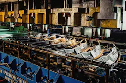
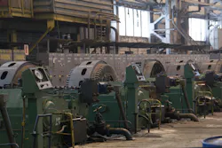
A mid-sized automotive stamping plant in the American Midwest ran a 2,200-kW hydraulic press for 11 years. The press worked. Parts came out on spec.
Maintenance crews serviced it on a calendar schedule — oil every 1,500 hours, filter swaps quarterly, a full teardown every 2 years.
Yet it still experienced two unplanned shutdowns per quarter. So, the plant's operations manager eventually agreed to a sensor retrofit. Within 8 months, unplanned downtime had fallen significantly, and the press was producing more parts per shift than before.
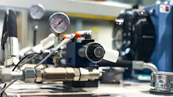
What changed? Nothing about the hydraulic circuit itself. The pump, the proportional valves, the manifold were all original equipment. What changed was visibility. A network of pressure transducers, flow meters, and temperature probes started feeding real-time data into the plant's control system, helping engineers monitor pressure, temperature, and flow behavior inside the system.
The sensors didn't fix anything, but they told the truth. And the truth turned out to be actionable.
That story is not unusual. Integration of sensors into hydraulic systems continues to prove beneficial for monitoring system performance and providing insight into potential maintenance issues.
Read the first article in this series “Hydraulic Sensors: Understanding the Types and Integration Strategies” to learn about the types of sensors commonly used in hydraulic systems and how they can be integrated into these systems.
This second of a two-part article series on hydraulic system sensors examines the measurable performance improvements sensors enable, and the genuine engineering challenges that come with deploying instrumentation in harsh environments — from calibration routines and signal conditioning to mounting geometry and power budgets.
Performance Improvements: What the Data Actually Shows
Sensors integrated into hydraulic systems can collect a range of data, offering machine owners opportunities to use that information to improve system performance and in turn their business operations.
In this section we examine the ways in which sensor data is being used to bring performance improvements to hydraulic systems in terms of efficiency, maintenance and motion control.
Energy Efficiency Gains in Variable Speed Pump Systems
The most consistent quantified benefit from hydraulic sensor integration is energy savings. According to a McKinsey report, fluid pumps account for roughly 15% of the European Union’s (EU) total energy use, highlighting a significant opportunity to improve the energy efficiency of hydraulic pumps and systems.
Smart pump systems comprised of variable displacement piston pumps paired with variable-speed drives and feedback from pressure and flow sensors can dramatically improve on that average.
A properly implemented load-sensing system with pressure and flow feedback typically achieves overall system efficiency of 60-75% in industrial press and injection molding applications. That's a 15-25 percentage point improvement over a fixed displacement, pressure relief-based system. In terms of energy cost for a plant running three shifts, the difference over 1 year can easily exceed the cost of the sensor package by a factor of ten.
The mechanism is straightforward: without flow sensing, the pump controller maintains a fixed standby pressure margin often 30-40 bar above the actual load demand to ensure adequate response. Installing flow sensors in the main supply and return lines can help a PLC (programmable logic controller) or drive controller implement load-sensing control, improving pump efficiency compared with fixed-displacement or poorly tuned variable systems.
Combined with variable-speed drive control of the prime mover, this reduces pump absorbed power in rough proportion to the flow reduction cubed following the affinity laws. A 20% reduction in pump speed reduces absorbed power by roughly 49%.
Predictive Maintenance: Quantifying the Maintenance Dividend
The maintenance case for sensor integration is equally compelling. Hydraulic system failures are rarely sudden catastrophic events. More often they're gradual deteriorations that accelerate into failure if not caught early. Seal wear, increased internal pump leakage, valve spool wear, filter bypass - all of these generate measurable signatures in pressure, temperature, and flow data before they cause downtime.
Field data from multiple industrial hydraulic installations with sensor-based condition monitoring consistently shows 40-60% reductions in unplanned downtime compared to interval-based maintenance programs. The mechanism is straightforward: instead of replacing components on a fixed schedule, some too early and some too late, maintenance is triggered by actual condition.
A pump showing increased case drain temperature and reduced volumetric efficiency in flow monitoring gets scheduled for replacement before it fails in production. The planned stop takes 2 hours. The unplanned failure would have taken 16.
Consider a mining application: a large underground loader operating in a high ambient temperature environment with water-contaminated hydraulic fluid as a persistent problem. Installing an in-line oil quality sensor measuring dielectric constant and water content in real time combined with an ISO cleanliness particle counter allowed the maintenance team to extend oil drain intervals by 35% during clean operating periods while catching contamination events within hours rather than days.
Component replacement costs dropped by 28% over 2 years, and the loader's availability rate improved from 82 to 91%.
Injection molding is another instructive case. A 650-ton machine running at 90 shots per hour generates enormous cycle-to-cycle pressure data. Monitoring injection pressure with a high-speed transducer logging data at 1 kHz allows the PLC to detect shot-to-shot variation that correlates with screw wear, check valve wear, and material viscosity changes.
When injection peak pressure variation across a 100-shot window exceeds ±3%, the process is flagged well before parts begin failing dimensional checks. This kind of in-process quality monitoring has allowed some processors to eliminate a substantial portion of their end-of-line inspection effort, with immediate ROI (return on investment) in labor and scrap reduction.

Precision and Repeatability in Motion Control
In applications requiring precise hydraulic motion such as servo presses, synchronized multi-cylinder lifts, and hydraulic test rigs, sensor integration directly enables performance that would otherwise be impossible.
A hydraulic servo press with integrated cylinder position and force sensors can achieve positioning repeatability of ±0.05 mm and force control accuracy of ±0.5% of set point across a full forming stroke. That level of performance was achievable with all-electric systems but previously required accepting the tradeoffs in force density, peak force capability, and cost that come with electromechanical drive systems.
For synchronized lifting, moving a large mold or structural component with multiple hydraulic cylinders in parallel requires position sensors on each cylinder feeding a synchronization controller to maintain leveling within 1-2 mm across spans of 5-10 m.
Without sensor-driven synchronization, differential settling under uneven load can twist and damage the lifted component. With it, the control system continuously compensates by modulating individual cylinder flows.
Challenges and Engineering Solutions
While there are many benefits to integrating sensors into hydraulic systems, doing so is not without its challenges. It is therefore important to understand what some of those challenges are and the design techniques to consider to address them.
In addition, it is necessary to understand the importance of calibrating these devices as well as how ROI can play a role in determining what sensors to employ.
Harsh Environments and Sensor Durability
Hydraulic environments are fundamentally hostile to electronics. High ambient temperatures, aggressive fluids, extreme vibration, and pressure transients all stress sensor components and connections.
Chemical compatibility between sensor wetted materials and the hydraulic fluid is non-negotiable: common hydraulic fluids range from standard mineral oil to water-glycol fire-resistant fluids (which attack brass and zinc alloys), phosphate ester fluids (which are incompatible with most elastomers), and biodegradable esters.
Stainless steel wetted parts are broadly compatible, but material suitability must be checked carefully for water-glycol and phosphate ester exposure.
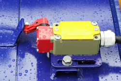
For environments with high-pressure cleaning or washdown, such as food and beverage production, some metalworking cell sensors rated to IP69K are required. That rating means the sensor survives a 80 C, 80 bar water jet at close range for 30 seconds. It's a meaningful specification, not just a marketing claim. Verify it before mounting expensive sensors in washdown areas.
Vibration is a common cause of premature sensor failure in mobile equipment and press applications. Beyond selecting sensors with appropriate mechanical resonance frequency (rule of thumb: natural frequency at least five times the dominant excitation frequency), pay attention to the connection between the sensor and the structure.
Rigid mounting on a vibrating hydraulic manifold transmits vibration directly to the sensor body. A short section of high-pressure hydraulic hose even 150 mm between the sensor port and the manifold acts as a vibration isolator and extends sensor life significantly.
Power Harvesting and Wireless Challenges
Running power cables to sensors in difficult locations inside mobile machine frames, in rotating equipment, and in submerged actuators can sometimes be impractical or impossible.
Power harvesting from the hydraulic system itself is an active area of development to address this. Small piezoelectric energy harvesters mounted in hydraulic lines can capture energy from pressure ripple and the cyclic pressure oscillation generated by pump pistons, typically at 6-12 times pump rpm. Available power is modest (1-50 mW depending on ripple amplitude and harvester size), but modern low-power sensor electronics can operate within that budget.
Inductive coupling through hydraulic cylinder walls, a technique used in some mobile equipment sensor packages, allows power and data transfer without any penetration of the pressure boundary. This approach requires careful design of the coupling geometry but eliminates the fundamental reliability risk of a dynamic seal around a signal cable. For new cylinder designs in mobile applications, it's worth evaluating from the start.
Signal Noise and Data Quality
High-vibration environments generate electrical noise that can corrupt sensor signals. Differential signal transmission (4–20 mA current loop or RS-485 with differential pairs) is far more noise immune than single-ended voltage signals, and should be the default for any sensor more than 2 m from its signal receiver.
For pressure sensors in high-EMI (electromagnetic interference) environments near large motors or welders, shielded cable with the shield grounded at the receiver end (not both ends, to avoid ground loops) is essential.
Signal filtering is the other half of the noise problem. Hardware RC filters at the sensor output can attenuate high-frequency noise before it enters the signal chain. Software filtering in the PLC moving averages, median filters, or exponential smoothing can clean up the remaining noise without excessively damping the response to genuine process events.
The key is understanding what bandwidth you actually need: a temperature signal valid to 1 Hz doesn't need a 10 kHz capable signal chain. Matching sensor bandwidth, cable specification, and filter settings to the actual measurement requirements simplifies the entire installation.
Calibration Routines That Hold Up in the Field
Sensor accuracy means nothing without a calibration program. Pressure sensors drift over time, typically 0.1-0.3% of full scale per year for quality piezoresistive devices, and temperature changes can affect zero and span.
A practical field calibration routine for hydraulic pressure sensors involves: isolating the sensor from the circuit with a valve, connecting a calibrated reference gauge or dead weight tester at the same port, and recording sensor output at three or five pressure points spanning the working range.
If sensor output deviates beyond the acceptable tolerance from the reference at any point, adjust the sensor trim if available or schedule recalibration/replacement based on the manufacturer’s specification.
For temperature sensors, a portable reference thermometer inserted into the hydraulic reservoir through a thermowell or dip tube provides a calibration check without disrupting system operation. Verification intervals should be set based on the application, manufacturer guidance, and the required accuracy, with more frequent checks for safety-critical functions.
Calculating Sensor ROI
The return on investment calculation for hydraulic sensor integration is often more straightforward than engineers expect. Take a system running 6,000 hours per year with a 100 kW average prime mover load.
A 20% energy savings from smart pump control with flow sensor feedback saves 120,000 kWh annually. At $0.10 per kWh, that's $12,000 per year in energy costs. A complete sensor package for that system can vary widely in cost depending on sensor type, installation, and control hardware.
Add the maintenance component: if sensor-based condition monitoring prevents one major hydraulic failure per year, a pump replacement that would have cost $8,000 in parts plus $4,000 in lost production during an unplanned 16-hour outage leads to another $12,000 in annualized savings.
Well-implemented hydraulic sensor projects can produce strong first-year ROI, but the return depends on the application, avoided downtime, and maintenance savings.
Future Directions: Where is Hydraulic Sensing Headed?
Sensor technology and the way it will be used in hydraulic components and systems will continue to advance in the years ahead.
One of the more interesting directions the industry is headed is the integration of sensors directly into manifold bodies during additive manufacturing.
Metal 3D printing, such as direct metal laser sintering and binder jetting, allows manifold designers to embed sensor housings, fluid passages, and even signal cable conduits into a single monolithic part. A hydraulic manifold with six integrated pressure measurement points and two temperature sensors, all feeding into a connector at the manifold face, can be produced as a single printed part. No external tees, no additional ports, no potential leak points. The manifold is also the sensor carrier.
This approach is still emerging as print costs remain high relative to machined manifolds for production volumes. But for demanding applications where compactness, leak integrity, and sensing density are all priorities, additively produced manifolds are increasingly viable. Several industrial automation suppliers are already offering them for precision motion control and test stand applications.
The longer term vision is hydraulic systems that optimize themselves. One way to achieve this is through an artificial intelligence (AI)-driven control layer with access to sensor data such as pressure, flow, and temperature which can help adjust hydraulic operation to reduce energy use while maintaining performance targets.
Early implementations of this concept may appear in precision manufacturing applications such as hydraulic servo presses where advanced control adapts to material variation to reduce scrap with limited operator intervention.
The sensor infrastructure is increasingly available, and control algorithms are maturing, so self-optimizing hydraulic control may expand beyond specialty applications in the coming years.
The foundation of all of it is accurate, reliable sensor data. The systems are only as intelligent as their inputs. You can't optimize what you can't measure. In hydraulic systems, we're still early in the process of measuring everything worth knowing.
This article was written and contributed by Faisal Mahmood on behalf of Such Limited, a developer of various sensor technologies.
About the Author
Faisal Mahmood
Faisal Mahmood is a digital marketing professional and technology content contributor specializing in robotics, automation, and IoT. He contributes high-quality, insight-driven content to authoritative platforms, helping simplify complex technologies for industry professionals.
