Once a drill rig strikes oil, there’s a limit to how quickly you can extract oil and gas from a single well. That’s why you so often see dozens of rigs spread across the landscape. But when rigs reach a reserve especially deep and even miles away underground, it’s more practical to move the rig for drilling at a new location rather than to build and erect another rig.
That’s where Columbia Industries LLC, Hillsboro, Ore., comes in. Columbia was instrumental in pioneering the oil drilling rig transport industry in 1974 by putting heavy land rig modules onto large axle systems. In 1982, the company introduced its mobile self-propelled wheel systems. Columbia’s first “walking” system utilized two separate modules weighing a total of 10.5 million lb for the Northstar Seal Island Alaska project in 2000.
Today, after successfully designing and building more than 40 active land rig walking systems deployed throughout North America and in Saudi Arabia, the largest to date can walk a four-module land rig in a full drilling configuration that weighs approximately 25 million lb. But, as Scott Van Raden, engineering manager notes, “There may be a limit as to how much weight our walkers can carry, but so far, we have not found it.”
“Walking systems,” Van Raden explains, “are less expensive per pound moved than a self-propelled wheeled system. They move very slowly and are best suited for pad drilling, batch drilling and island projects. The key here is that they can support nearly unlimited weight, and still apply low ground bearing pressure to the surface below. This is very important for island projects and poor soil types because it reduces preparation costs before drilling.”
“Walking” hydraulically
A walking sequence starts with a set of vertically mounted cylinders extending to lift the load. Once the cylinders have extended 2 to 4 in., a set of horizontally mounted cylinders drives the load (which is now supported by rollers) forward. The rollers travel on a 4-ft wide by 60-ft long sub beam, or foot. Depending on individual module weight, two to six travel cylinders and the rollers underneath them act together as an integral unit. Once the horizontal cylinders have extended about 4 ft, the vertical cylinders then retract — returning the system back onto the foot. The sequence repeats until the load reaches its final position.
Vane pumps ideal for walking sequence
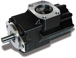
The pumps used in Columbia’s walking system drive are Parker Hannifin T6CC vane pumps, which provide a single inlet and two outlets. Designed to be self-wear compensating, these pumps tolerate contaminants and maintain high efficiency over their service life. High efficiency means an overall longer life for the hydraulic system. High lifetime efficiency ensures safe and reliable output from the pumps throughout their service.
The Parker vane pump is also quiet, which is important for communications between the operations team while walking the platform. The high pressure capability (4000 psi) of this pump operating at Columbia’s relatively low system pressures makes it extra reliable and quiet because it operates well below its full potential. The inlet and fluid capabilities of the pump are features that make it a top choice for the elevation and temperature conditions in which these machines must operate.
“Our largest (walking) system to date,” points out Van Raden, “has drill, utility and mud modules that are lifted by six hydraulic cylinders each. A pipe barn module is the largest load we have mobilized to date, using nine lifting zones and 18 hydraulic lift cylinders. When all four modules are assembled into the drilling configuration, the lift capacity of the fully loaded system is approximately 25 million lb.”
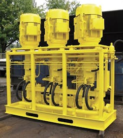
Parker Hannifin T6CR and T6CC double vane pumps provide both the lift and travel pressure for the hydraulic cylinders’ drill, utility and mud modules. Two vane pumps supply six lift cylinder modules. For a pipe storage module, electric motors on a hydraulic power unit (HPU) drive a Parker/Denison T6CR-010 pump with a through shaft that drives a T6CC-010-010 double pump. Three motors are incorporated to raise the nine lifting zones, each with a lift pressure of approximately 1500 psi. However, each lifting circuit is individually set to ensure that the load — which can vary in weight from lifting zone to lifting zone — goes up level and at the same speed until all lift cylinders have raised their load.
“Each walk step is a two-minute cycle,” points out Van Raden, “The vane pumps are used for both the lift and travel steps because the two circuits are not used at the same time.” Pump pressure for the traveling cylinder is approximately 1000 psi. A separate HPU for the walking system is incorporated into each of the four modules.
The rollers are also part of the steering system and are turned and positioned before weight is applied. Each module can be steered from the front, back or both ends when sharp turns are required. This linked steering system is very precise. Steering, lifting, travel, and set down operations are performed by the cab operator.
“In our 25 million-lb system,” notes Van Raden, “the walking modules for drilling, utility and power measure about 50 ft by 100 ft. The pipe barn module is 170 ft by 180 ft, with a footprint of 3600 ft2 for the module’s sub beams. The nine lifting zones and 18 hydraulic lift cylinders inside the walking system beams are needed because of the weight and the way the weight is configured inside the barn. There can be a full load of heavy 90-ft drill pipe, a light pipe load, or no pipe. Yet, the module still must remain level during each walk sequence. In batch drilling, for example, the objective is to take the entire load of drill pipe needed to drill the well. The pipe is stacked vertically in the derrick, or setback. This allows the operator to drill a well quickly, utilizing a continuous feed of 90 ft long pipe sections connected together.”
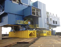
In an island application, the independent rig modules receive their final fabrication and assembly into the drilling configuration. Then the modules are independently walked in a semi-linked condition within several inches of each other at the same pace, but without contact. This coordinated effort keeps all of the connections in place.
A four-module application uses four module operators — two operators per cab — where they can speak and hear each other as they coordinate the move. Once assembled into the drilling configuration, the whole unit is walked and set to drill the first (injection) well. On completion of the injection well, the linked drilling configuration is then walked to drill the first production well.
“The linked walking system,” Van Raden stresses, “allows the interconnected modules to be moved simultaneously with steering options that include forward, backward, right, left, crab, and complementary movement for precise pad positioning.”
Chad Todd and Dave Ebert are both with Parker Hannifin's Hydraulic Pump Div., Marysville, OH. For more information, call (937) 644-4435 or visit www.parker.com/hydraulicpump. For more information from Columbia Industries LLC, visit www.columbiacorp.com.
Hydrostatic pump powers wheeled drive system
In 1997,” notes Scott Van Raden, “our redesign of the drive system for our self-propelled wheeled systems incorporated the Parker Gold Cup hydrostatic transmission. The jacking and steering system incorporated Parker PV series piston pumps, and a Parker vane pump was designed in for the braking circuit.”
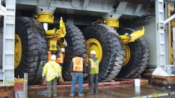
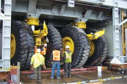
An HPU and high-pressure hydraulic system is used to propel these 50-ft. wide by 100-ft. tall rig-mounted modules that have tires 12-ft. tall and 4-ft. wide mounted on wheels bolted to Columbia drive axles, each with a maximum capacity of 680,000 lb. Total carrying capacity for a self-propelled wheeled module is about 2.5 million lb. Each module is powered by a diesel-driven generator that supplies power to electric motors of the hydraulic power unit. Module steering and braking is controlled by an operator from a cab on the front. If necessary, each axle can be turned 90° to drive the configuration sideways.
“The low-pressure piston pump system used for jacking and steering,” Van Raden explains, “has a maximum of 1650 psi for the jacking circuit and 2000 psi for the steering circuit. Each circuit has separate pumps.”
“With a 5000-psi Gold Cup hydrostatic pump,” continues Van Raden, “the drive system gives us forward and rearward travel with speeds up to 212 mph maximum, and down to an absolute dead creep speed of 100 ft/hr. Such a slow speed is needed as the drilling rig module approaches the well to ensure that the center of the drill pipe is directly on the well center to be drilled. Placement accuracy has to be within 116 in.
“The Gold Cup pumps have a built-in charge pump, which provides the required replenish/flow pressure to the closed circuit transmission,” Van Raden stresses. “Plus, visual indicators mounted on the outside of the pump and motor cases allow our technicians to see if the internal components of these mobile units are following the control signals sent to them. This makes it considerably faster and easier to troubleshoot any problem that might arise. Finally, we continue to use Gold Cup pumps for our wheeled systems for their proven service and reliability record.”
About the Author
Chad Todd
and David Ebert

Leaders relevant to this article:
