Digital resolution and related subjects — Part 2
Editor's note: This is the second installment in a seven-part series on digital resolution and other subjects. Read the rest now: Part 1, Part 3, Part 4, Part 5, Part 6, and Part 7.
The number of bits needed in a transducer relates directly to the ultimate error that can be tolerated in the application. For example, suppose you must control the position of a cylinder with an error of no more than ±0.010 in., and the cylinder is 10 in. long. The question is, “How many bits are needed at the transducer output in order to measure the cylinder position within the required tolerance?”
With digital devices, the uncertainty (error) is ±1 least significant bit (LSB). We must select the number of bits in the transducer signal so that one bit of uncertainty is within the tolerance. A rule of thumb requires that the error in the transducer to be 110 of the final error in the control. Therefore, we have to ensure that one bit translates to no more than 0.001 in.
The formula for calculating the minimum number of bits is:
N ≥ Log (XT ÷ ΔX) Log (2)
Where N is the minimum number of bits,
XT is the total measurement range, and
ΔX is the error limit.
In the example at hand, ΔX = 0.001 in. and XT = 10 in., so N is 13.29. Therefore, we need a transducer with at least 14 bits of sensitivity because N must be an integer.
If only 13.29 bits are needed, and we have 14, the next question is, “What will the actual resolution be for the transducer?” It is only necessary to solve the equation for the actual ΔX, which produces:
ΔX= XT ÷ 2N
If N is 14, and the total cylinder travel is 10 in., then our resolution actual resolution is 0.00061 in.
What is resolution?
“Resolution” is one of most abused words in the control systems and measurement lexicon. The definition that has served me well for an entire career is: resolution — minimum discernible change.
In analog systems, resolution is a difficult quantity to pin down. It requires repeated tests and statistical processing of the test results to be done correctly. That subject is justifiably assigned to technologists with the necessary expertise, and will not be pursued further. On the other hand, in digital systems, resolution is easy to understand; it is simply one bit. It is the smallest change we can see in the output. In our example, one bit translates into 0.00061 in., so that is the resolution in inches when a 14-bit position transducer is used on a 10-in. stroke cylinder.
The abuse of resolution comes when dealing with highly precise equipment. We read of “high resolution devices,” when we mean exactly the opposite! Look at resolution quantified. The quality, or goodness, of the transducer is improved and is more valuable as the resolution gets smaller and smaller, and yet we say it is high resolution. The ultimate corruption comes with analog devices, where the smallest discernible change approaches zero. However, it is referred to as having “infinite resolution.” No wonder we don’t understand each other.
Position encoders
There are many types of position transducers. However, in the modern electrohydraulic system, a few have come to prevail in the industry. The first one we’ll examine is the incremental optical encoder.
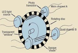
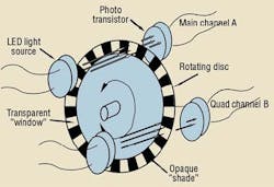
A simplified schematic of the incremental encoder is shown in Figure 1. It contains a thin disk with an outer periphery having a series of alternating radial segments of transparency and opaqueness. They are formed with great precision and repeatability. The precision with which the segments are placed has absolute control over the errors of the encoder.
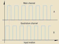
A main light emitting diode (LED) projects onto the disk to detect whether a “window” or a “shade” is positioned in front of it. If a window is present, the transmitted light will impinge on a receiving phototransistor. The transistor conducts when there is light, and it shuts off when dark. When the input shaft is turning, the transistor current is a series of pulses of on and off, as shown in Figure 2, for the main channel.
Mechanically displaced by an integer number of radial segments, plus one-half a segment, is another LED-photo-transistor-sensing pair, called the quadrature channel, Figure 1. The quadrature channel produces a train of pulses that is displaced in phase by 90°, that is, when the main channel is high and at mid-pulse, the quadrature pulse makes a transition from high to low, as in Figure 2.
The use of the two channel encoder configuration is two-fold. First, with special signal conditioning circuits (not shown in any of the figures), edge detection can be implemented in which the ultimate pulse train consists of one pulse for each transition on each channel. That is, the leading edges of both channels can be detected as well as each trailing edge. This is called edge counting, and has the effect of providing four times finer resolution.
Second, a single train of pulses has no directional information. For example, if you observed the pulse train of either channel on an oscilloscope, you would not be able to tell which direction the input shaft was moving. However, when the quadrature channel is added, you can tell in which direction the disk is rotating. If the quadrature channel goes from high to low while the main channel is high, the shaft is turning forward. If the quadrature channel goes from low to high while the main channel is high, the direction of travel is backward.
Perhaps the most critical parameter of the incremental encoder is the number of segments per revolution. The one shown in Figure 1 has only 36 segments of alternating window and shade, which produces only 18 pulses per revolution. The resolution of the encoder is the reciprocal of the number of pulses per revolution: in this case, 1/18 of a revolution, or 20°.
The incremental encoder can be used for measuring position merely by counting the pulses fed into the electronic counter. But because a simple counter cannot distinguish direction of rotation, the direction bit from the fwd-rev logic module tells the counter to add or subtract the current pulse to the counter contents. Thus, the total count in the counter register is a measure of the total change in position since the counter was zeroed.
Encoder shortcomings
The low price of incremental encoders is counteracted by its shortcomings. When power is removed from the counter, it loses its contents. When it is subsequently re-powered, it would normally go to zero. However, the actual machine axis will be at its last position. For this reason, machine power-up normally consists of a zeroing procedure where the machine axis is driven to a known position that is controlled by, for example, a hard mechanical stop. The counter is set to a count value that corresponds to this so-called “home position.” From that moment on, barring any subsequent errors, the counter will indicate the position of the axis relative to home position. The electronic counter can be equipped with a battery backup so that position information is not lost at power down time. Flash, or other non-volatile memory can also be implemented.
In spite of these preventive actions, noise can cause false counts — either by adding a noise pulse that the counter will add to its current content, or by suppressing a genuine countable pulse, resulting in missing a count. The only method for dealing with these errors is for the machine to periodically seek out the home position so that the counter can be reset to a correct value while occupying a known position.
In machines that go through a regular cyclic process, it means sending the axis into the hard stop, and then setting the counter, just as is done at machine power-up. Some machines can be programed to perform a homing exercise every machine cycle, depending on the nature of the process being performed. The absolute encoder was built to circumvent these problems and will be covered in the next edition of “Motion Control.”
Speed measurement
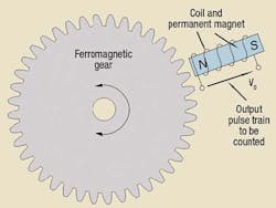
Incremental encoders with only one channel often are used for speed control systems using rotational actuators, such as a hydraulic or electric motor. Speed is determined by measuring the frequency of the encoder output. The most common type of single-channel encoder is the magnetic pickup, Figure 3, which uses a magnet wrapped by a coil and an irregular rotating ferromagnetic member (such as a gear) so that the proximity of the coil-magnet to the gear teeth results in a voltage being induced in the coil. If the gear has 60 teeth, then the frequency, in Hz, is exactly the same as the speed in rpm. The output of the simple magnetic pickup goes to zero as the speed goes to zero.
If you need to use the magnetic pickup as a position encoder and as a speed pickup, it must operate down to zero speed. This is easily accomplished by using a Hall-effect pickut. The Hall-effect magnetic sensor detects the magnetic field strength without the need for a relative velocity. Therefore, it will generate a reliable pulse train right down to zero speed.


